Brake-shoe-type centrifugal clutch

A centrifugal clutch and brake block technology, applied in the field of clutches, can solve the problems of fast decay of the spring force, reduction of the coupling speed of the centrifugal clutch, engine damage, etc., and achieve the effect of relatively small deformation of the work, insignificant attenuation of the spring force, and stable combination speed.

Pending Publication Date: 2018-07-31
XIANYANG CHAOYUE CLUTCH
View PDF7 Cites 5 Cited by
  • Summary
  • Abstract
  • Description
  • Claims
  • Application Information

AI Technical Summary

Problems solved by technology

This structure has the following defects: 1. There must be enough space between the centrifuges to place tension springs, so the design of the centrifuges is limited. Under the condition of certain external dimensions, the torque that can be transmitted is small. In order to meet the large torque In the working condition, the clutch with this structure can only enlarge the shape, resulting in increased processing costs and inconvenient installation; 2. Generally, the number of springs is large, it is inconvenient to hang the springs, and the adjustment of the spring force cannot be consistent, resulting in the centrifugal body and the driven 3. In order to leave space for the centrifugal body as much as possible, the number of tension spring coils is often small, the relative deformation is large during work, and the spring force decays quickly, resulting in the centrifugal clutch Combined with the decrease in speed (the speed when the centrifugal body overcomes the spring constraint force and starts to contact the follower), the engine will drive the working machine to rotate before it is fully started, causing damage to the engine

Method used


Image

  • Brake-shoe-type centrifugal clutch
  • Brake-shoe-type centrifugal clutch
  • Brake-shoe-type centrifugal clutch

Examples


Embodiment Construction

[0029] The present invention will be described in further detail below in conjunction with the accompanying drawings.

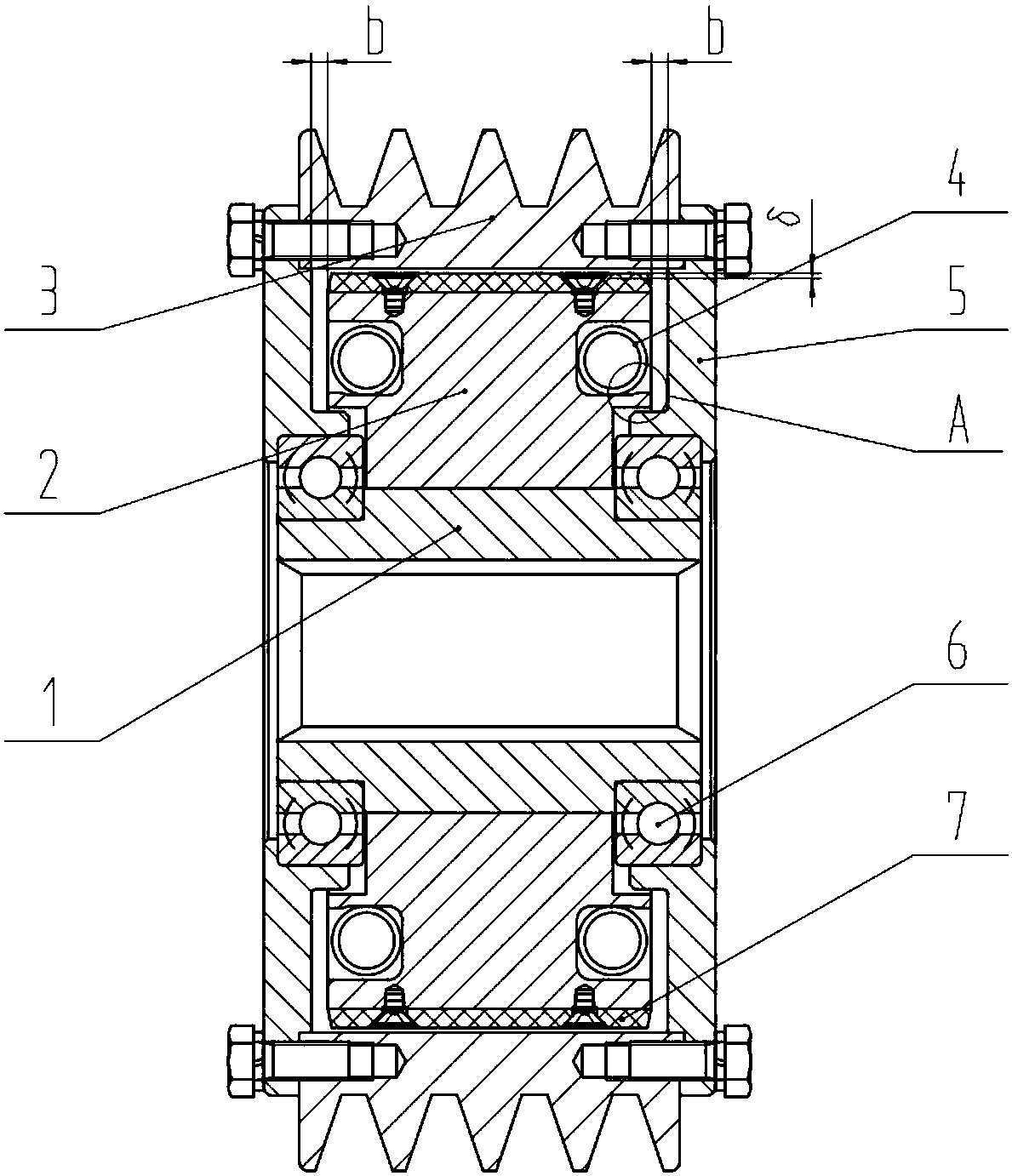
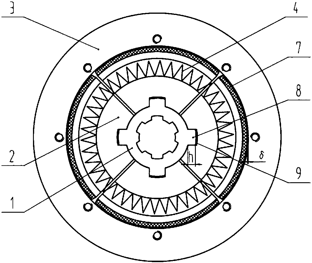
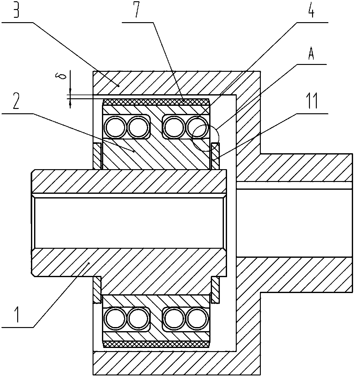
[0030] Such as figure 1 As shown: the active part 1 is a hollow shaft, the inner hole is provided with keyways or internal splines, several bosses / grooves are uniformly arranged on the outer circle, and several fan-shaped centrifuges are arranged on the outer side of the outer circle corresponding to each boss / groove 2. There is only a slight gap between the centrifugal bodies 2, and all the centrifugal bodies 2 form a complete circle surrounding the active part 1. There is a groove / boss on the inner diameter of the centrifuge 2, the groove / boss is just nested on the boss / groove of the active part 1, and can slide up and down, and the active part 1 and the centrifuge are nested through this concave and convex 2 can be rotated together. For balance, the grooves / bosses should be arranged symmetrically along the center of the centrifugal body 2 . The end face...


PUM


Abstract

A brake-shoe-type centrifugal clutch comprises a driving piece and centrifugal bodies. The centrifugal bodies are arranged on the outer side of the driving piece in a matched mode, the centrifugal bodies form a whole circle embracing the driving piece, and trace gaps exist between the centrifugal bodies; the centrifugal bodies are arranged outside the driving piece and can slide up and down; circular arc grooves are formed in the two sides of the combined rear end faces of the centrifugal bodies and connected in an end-to-end mode to form a complete ring groove; and ring-shaped tension springsare arranged in the ring groove. A tubular driven piece is arranged outside the centrifugal bodies, an appropriate gap exists between the centrifugal bodies and the driven piece in the radial direction; the driving piece and the driven piece are centered and rotate coaxially; and when the driving piece rotates and enables centrifugal force generated by the centrifugal bodies to be larger than constraining force of the ring-shaped tension springs, the centrifugal bodies and the driven piece make contact to transmit the torque. The ring-shaped tension springs do not occupy the circumferential space, the mass of the centrifugal bodies is large relatively, the generated centrifugal force is also larger, and thus the rated torque of the centrifugal clutch is improved; and the brake-shoe-type centrifugal clutch has the characteristics that the manufacturing process is simple, the transmitted torque is large, performance is stable, and the service life is long.

Description

technical field [0001] The invention relates to the technical field of clutches, in particular to a brake block type centrifugal clutch. Background technique [0002] A centrifugal clutch is a clutch that relies on the centrifugal force generated by the centrifugal body to achieve automatic separation or engagement. It is usually composed of a driving part, a centrifugal body, a driven part, a spring, etc. When the active part does not rotate or the rotating speed is low, the centrifuge is constrained by the spring to approach the active part and there is a gap between the active part and the passive part, and the active part will not drive the passive part to rotate. When the speed of the driving part increases, the driving part drives the centrifuge to rotate together and generate centrifugal force. Under the action of the centrifugal force, the centrifuge contacts the surface of the driven part and generates friction. At this time, the centrifuge connects the driving part...

Claims


Application Information

Patent Timeline
Patent Type & Authority Applications(China)
IPC IPC(8): F16D43/14
CPCF16D43/14
Inventor 任旭鹏李勇张进利豆相如
Owner XIANYANG CHAOYUE CLUTCH
Why Eureka
Try Eureka