Disk clamping device

A technology of clamping device and clamping rod, which is applied in the field of disk clamping device, can solve the problems of insufficient reliability of loading device and low performance of disk clamping device, and achieve the effect of stable pressing force and low cost

Inactive Publication Date: 2008-12-10
PANASONIC CORP
View PDF7 Cites 0 Cited by
  • Summary
  • Abstract
  • Description
  • Claims
  • Application Information

AI Technical Summary

Problems solved by technology

This has the problem that the performance of the disk clamping device is low and the reliability of the loading device is insufficient.

Method used


Image

  • Disk clamping device
  • Disk clamping device
  • Disk clamping device

Examples


no. 1 Embodiment

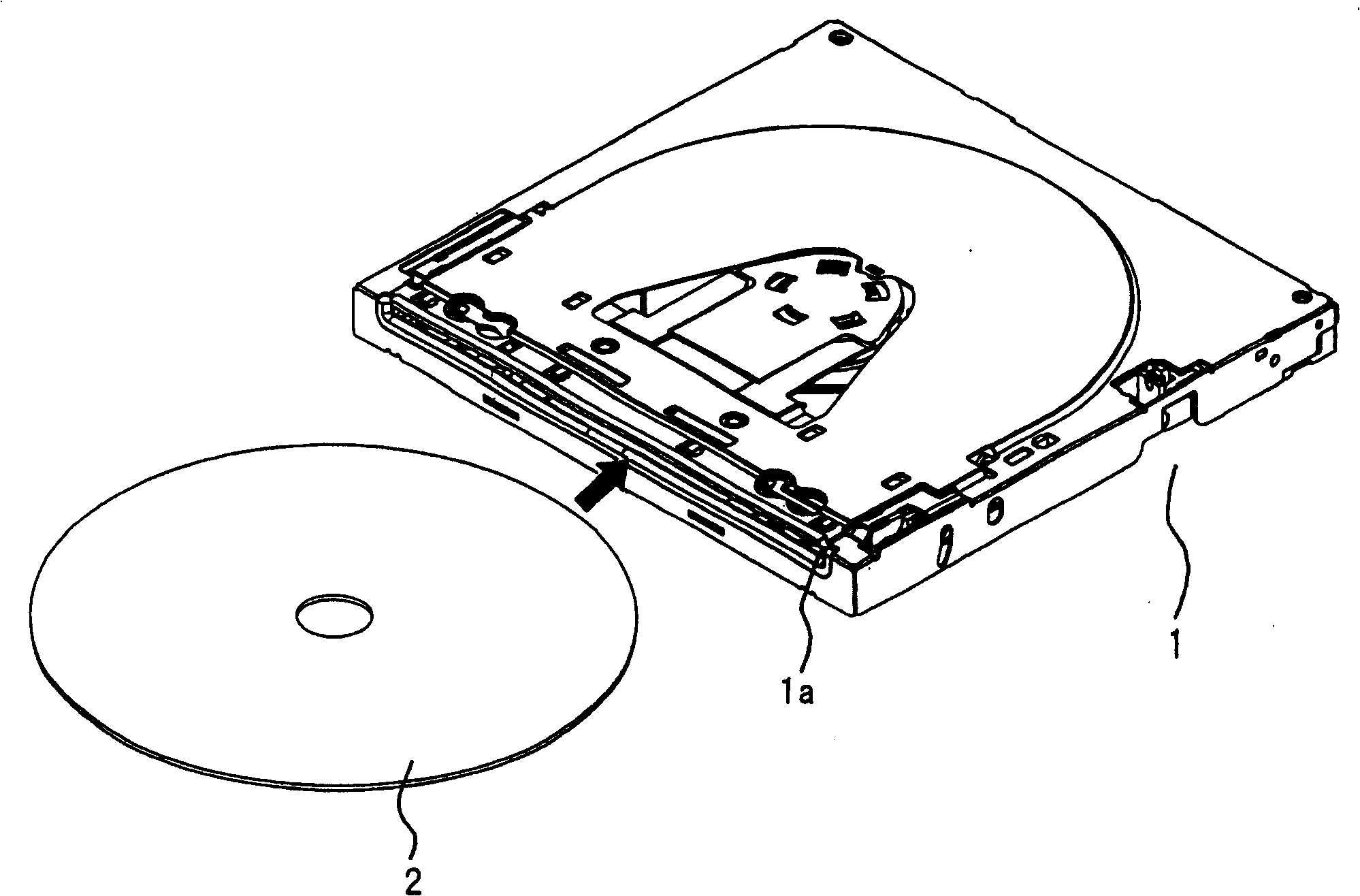
[0041] refer to Figure 1 to Figure 8 , the loading device provided with the disc clamping device according to the first embodiment of the present invention will be described. figure 1 It is a diagram showing a schematic configuration of a slotting system loading device in this embodiment. figure 1 In the loading device 1, when a disk 2 is inserted from the disk insertion port 1a, a part of the inserted disk 2 is clamped and loaded into the device, and the disk 2 is seated on the turntable (turntab1e) inside the loading device 1. given location.

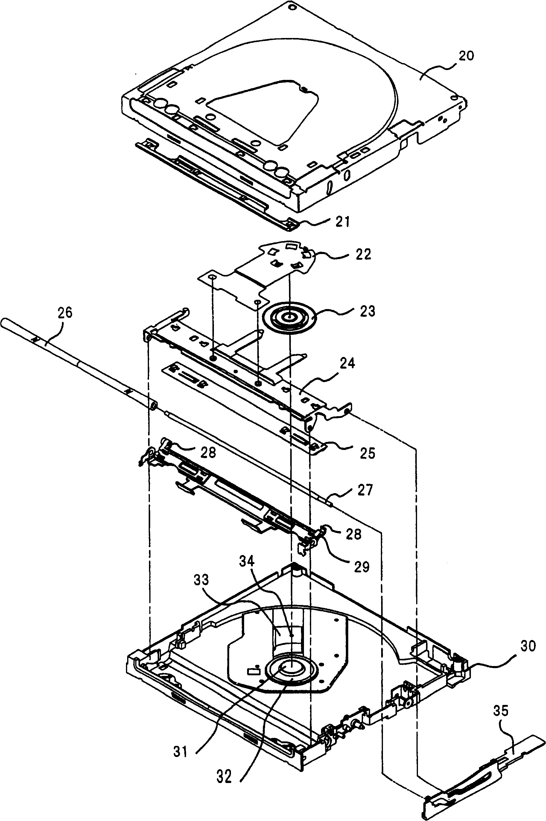
[0042] figure 2 express figure 1 An exploded perspective view of the loading device 1 in .

[0043] Disk insertion port 1a ( figure 1 ), formed by the base plate 20 and the mechanical base plate 30. The disc guide 21 is fixed near the disc insertion opening 1 a of the base pan 20 .

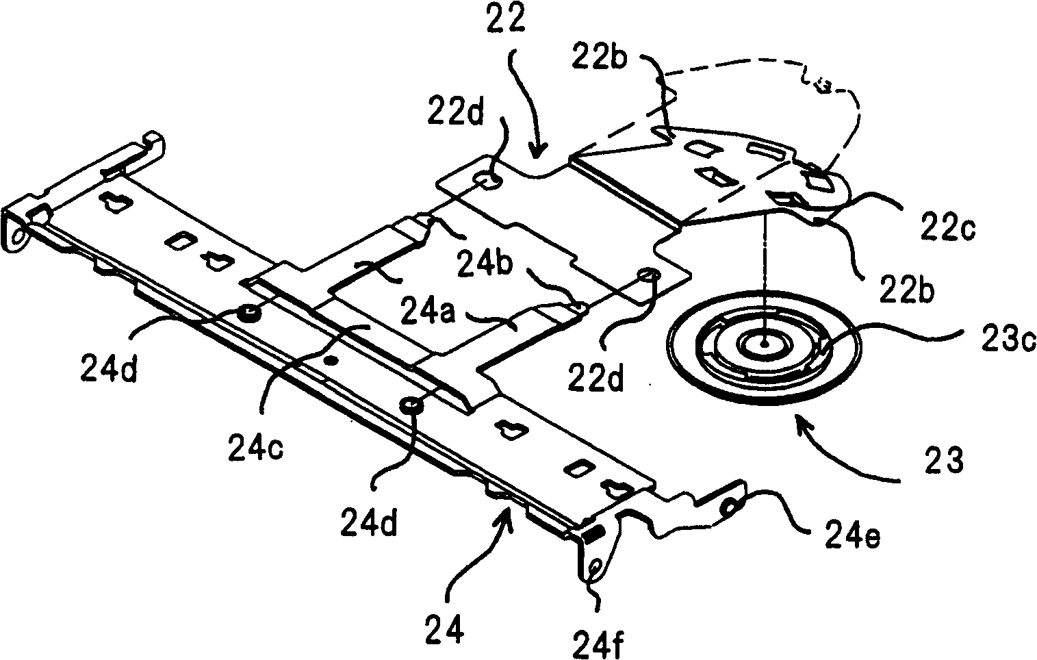
[0044] A leaf spring 22 is fixed on one side in a clamping lever 24 . The jig 23 is freely rotatably supported by the back of the leaf spring 2...

no. 2 Embodiment

[0073] Referring to Figs. 9 to 11, a description will be given of a loading device including a disc clamping device according to a second embodiment of the present invention. FIG. 9 is a schematic view showing the outline of the configuration of the slotting system loading device of the present embodiment. In FIG. 9, the loading device 100 of this embodiment, when inserting the disk 2 from the disk insertion port 100a, clamps a part of the inserted disk and carries it into the device, so that the disk 2 is seated on the inside of the loading device 100. The given position of the turntable.

[0074] FIG. 10 shows an exploded perspective view of the loading device 100 shown in FIG. 9 . In Fig. 10 , the point of having a leaf spring 22' instead of the leaf spring 22, the point of having a magnet 101 below the jig 23, and the point of having an adsorption plate 102 above the centering member 31, and figure 2 The loading device 1 of the first embodiment shown is different. In o...


PUM


Abstract

A disc clamping device having: a clamp lever supported freely rotatable; a plate spring one side of which is fixed to the clamp lever; and a clamp facing a turntable on which a disc is placed. The position of the leaf spring is supported in a freely rotatable manner, and the disk is pressed against the turntable by the turning action of the clamping lever, wherein the clamping lever has a support for the leaf spring. The arm portion, the leaf spring, has a flange portion supported by the arm portion, and the leaf spring is pressed by the arm portion of the clamp lever in a state where the clamp is not pressing the disc. The flange portion of the clamp is supported, the leaf spring is in an elastically deformed state, and generates an elastic force downward, that is, in the pressing direction of the clamp, and the leaf spring is acted upon by the elastic force. Accordingly, the present invention provides a disc clamp device that reduces fluctuations in pressing force corresponding to fluctuations in the stroke of the clamp lever.

Description

technical field [0001] The present invention relates to a disc clamping device. More particularly, it relates to a disc clamping device for pressing an inserted disc against a turntable provided in a disc loading device for loading a disc-shaped recording medium such as a CD or DVD. Background technique [0002] In recent years, as a device for loading disc-shaped recording media such as CDs and DVDs (hereinafter simply referred to as "discs"), there has been known a device in which a disc is directly inserted into the device without using a tray on which the disc is placed. Slotted loading device. [0003] This slot-type loading device grips a part of the inserted disk, and carries it into the device so that the disk is seated at a predetermined position on the turntable. The slot-type loading device does not require a tray for loading the disk, so it can be thinner than a loading device using a tray. [0004] In the aforementioned slot-type loading device, in order to r...

Claims


Application Information

Patent Timeline
Patent Type & Authority Patents(China)
IPC IPC(8): G11B17/028
Inventor 山崎卓人森冈幸生石川和雄吉田则胜
Owner PANASONIC CORP
Why Eureka
Try Eureka