
Hydrogen production from an oxyfuel combustor

Inactive Publication Date: 2007-03-01
CLEAN ENERGY SYST
View PDF77 Cites 98 Cited by
  • Summary
  • Abstract
  • Description
  • Claims
  • Application Information

AI Technical Summary

Benefits of technology

[0014] Another object of the present invention is to provide a method and system for low cost hydrogen production.
[0016] Another object of the present invention is to provide a hydrogen production and power generation system utilizing hydrogen and energy stored within a hydrocarbon fuel or other hydrogen containing fuel without atmospheric emissions.
[0017] Another object of the present invention is to provide a power generation system for low cost high volume production of hydrogen as well as some electric power when electric power demand is low and a greater amount of electric power when electric power demand is high.

Problems solved by technology

One challenge faced for widespread hydrogen utilization is the lack of low cost high volume convenient sources of hydrogen.
One obvious drawback of such a system for generating hydrogen is that the remaining hydrogen depleted syngas still generates significant pollution, and especially carbon dioxide and oxides of nitrogen when combusted with air and expanded to generate electric power.
Thus, while hydrogen is produced for the benefit of the environment, such systems correspondingly also emit greenhouse gases and other pollutants, undermining the very purpose for which the hydrogen is originally being produced.
However, electrolysis is currently prohibitively expensive in that it requires a significant electric current to achieve electrolysis.
Hence, electrolysis systems today are not economical for large scale hydrogen production.

Method used


Image

  • Hydrogen production from an oxyfuel combustor
  • Hydrogen production from an oxyfuel combustor

Examples


Embodiment Construction

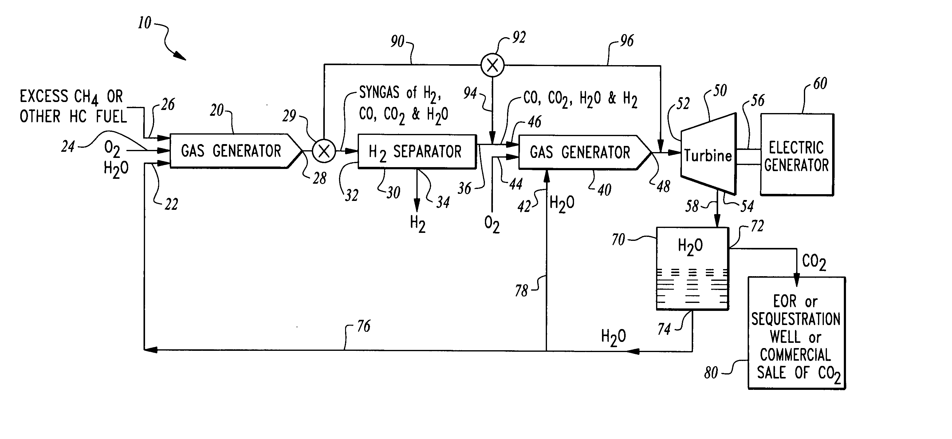
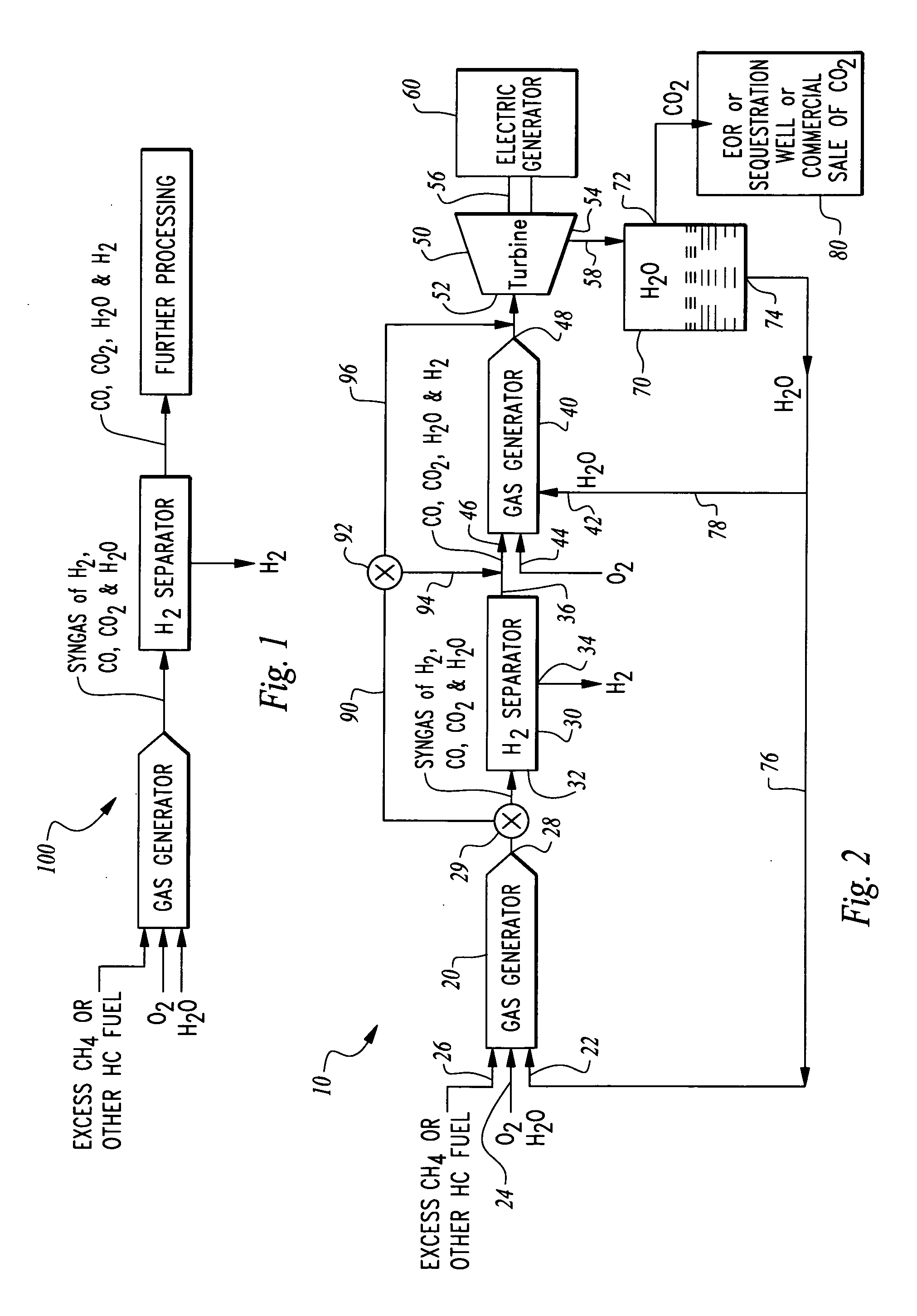
[0021] Referring to the drawings, wherein like reference numerals represent like parts throughout the various drawing figures, reference numeral 10 (FIG. 2) and reference numeral 100 (FIG. 1) are directed to systems for generation and separation of hydrogen from a hydrogen containing fuel and in conjunction with an oxyfuel combustor, such as a gas generator 20. With this invention hydrogen is produced and separated and power generation additionally optionally occurs, with no atmospheric pollution or release of greenhouse gases (especially CO2) into the atmosphere.

[0022] In essence, and with particular reference to FIG. 2, basic details of a power generation and hydrogen production system are described according to a preferred embodiment. The system 10 utilizes a gas generator 20 which combusts a hydrogen and carbon containing fuel, such as methane, with oxygen. The gas generator is operated “fuel rich” so that the gas generator 20 produces products of combustion including hydrogen ...


PUM


Abstract

A system is provided for hydrogen production from a hydrogen and carbon containing fuel combusted within an oxyfuel combustor. The oxyfuel combustor combusts hydrogen and carbon containing fuel with oxygen at a non-stoichiometric ratio, typically fuel rich. In such an operating mode, products of combustion include steam, carbon dioxide, carbon monoxide and hydrogen. These products of combustion are then passed through a hydrogen separator where hydrogen is separated. Remaining products of combustion can be optionally combusted at a stoichiometric ratio with oxygen in a second oxyfuel combustor discharging substantially only steam and carbon dioxide. A turbine can be provided downstream from the gas generator to produce power and eliminate carbon monoxide from the system. The system can be operated in a second mode where the gas generator combusts the fuel with oxygen at a stoichiometric ratio to maximize electric power generation without hydrogen production at periods of peak electric power demand.

Description

CROSS-REFERENCE TO RELATED APPLICATIONS [0001] This application claims benefit under Title 35, United States Code §119(e) of U.S. Provisional Application No. 60 / 707,326 filed on Aug. 10, 2005. FIELD OF THE INVENTION [0002] The following invention relates to combustion based power generation systems and particularly those which can also produce hydrogen. More particularly, this invention relates to power generation systems which combust oxygen and a hydrogen and carbon containing fuel in a gas generator which operates fuel rich to leave hydrogen separate from water within the products of combustion, and which further include a separator to separate the hydrogen from other products of combustion. BACKGROUND OF THE INVENTION [0003] Long range energy planners are placing increasing importance on the utilization of hydrogen as a power generating fuel, due to the pollution minimizing characteristics (and particularly avoidance of greenhouse gas emissions such as carbon dioxide) associated...

Claims


Application Information

Patent Timeline
IPC IPC(8): F02C6/00
CPCC01B3/36C01B2203/0255C01B2203/0405C01B2203/043C01B2203/047C01B2203/0475C01B2203/0495C01B2203/06C01B2203/84F01K21/04F02C3/22F02C6/10H01M8/0618H01M8/0643Y02E20/344Y02E20/34Y02E60/50
Inventor BRANDT, HARRYBRANDT, MURIEL R.ANDERSON, ROGER E.PRONSKE, KEITH L.VITERI, FERMINMACADAM, SCOTT
Owner CLEAN ENERGY SYST
Learn More