
Methods and apparatus for hot air sterilization of medical instruments

Inactive Publication Date: 2007-02-22
COLTENE WHALEDENT INC
View PDF1 Cites 24 Cited by
  • Summary
  • Abstract
  • Description
  • Claims
  • Application Information

AI Technical Summary

Benefits of technology

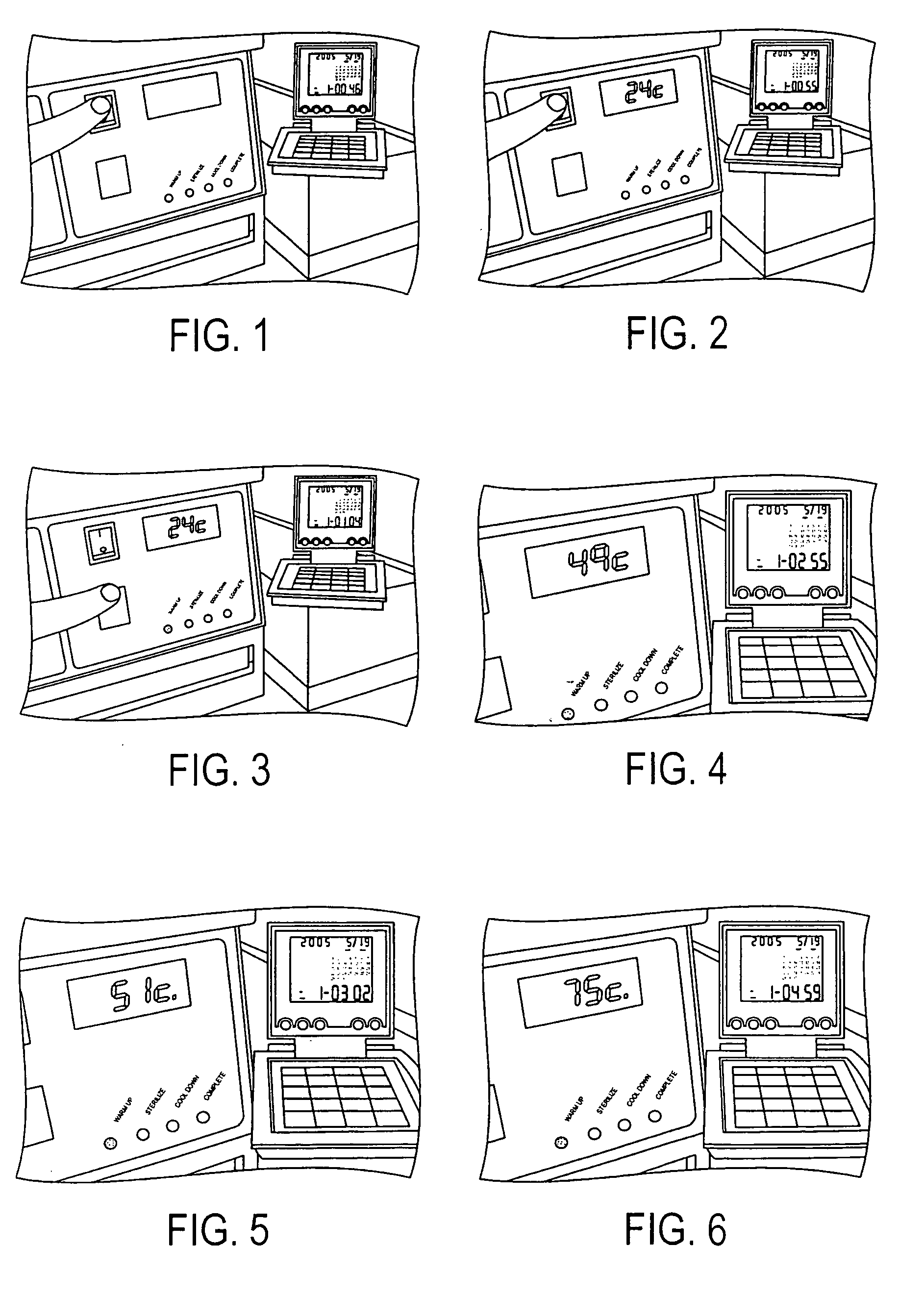
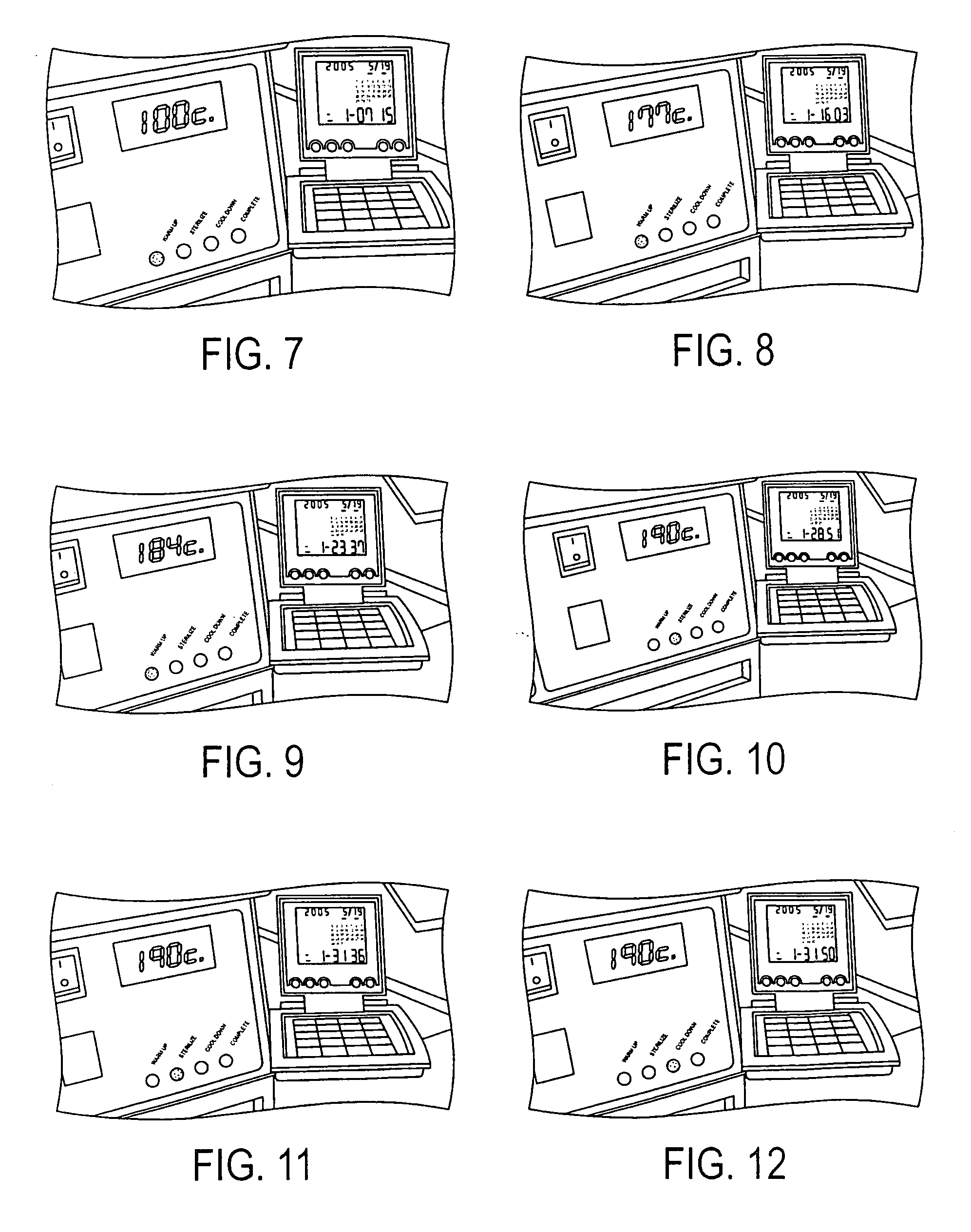
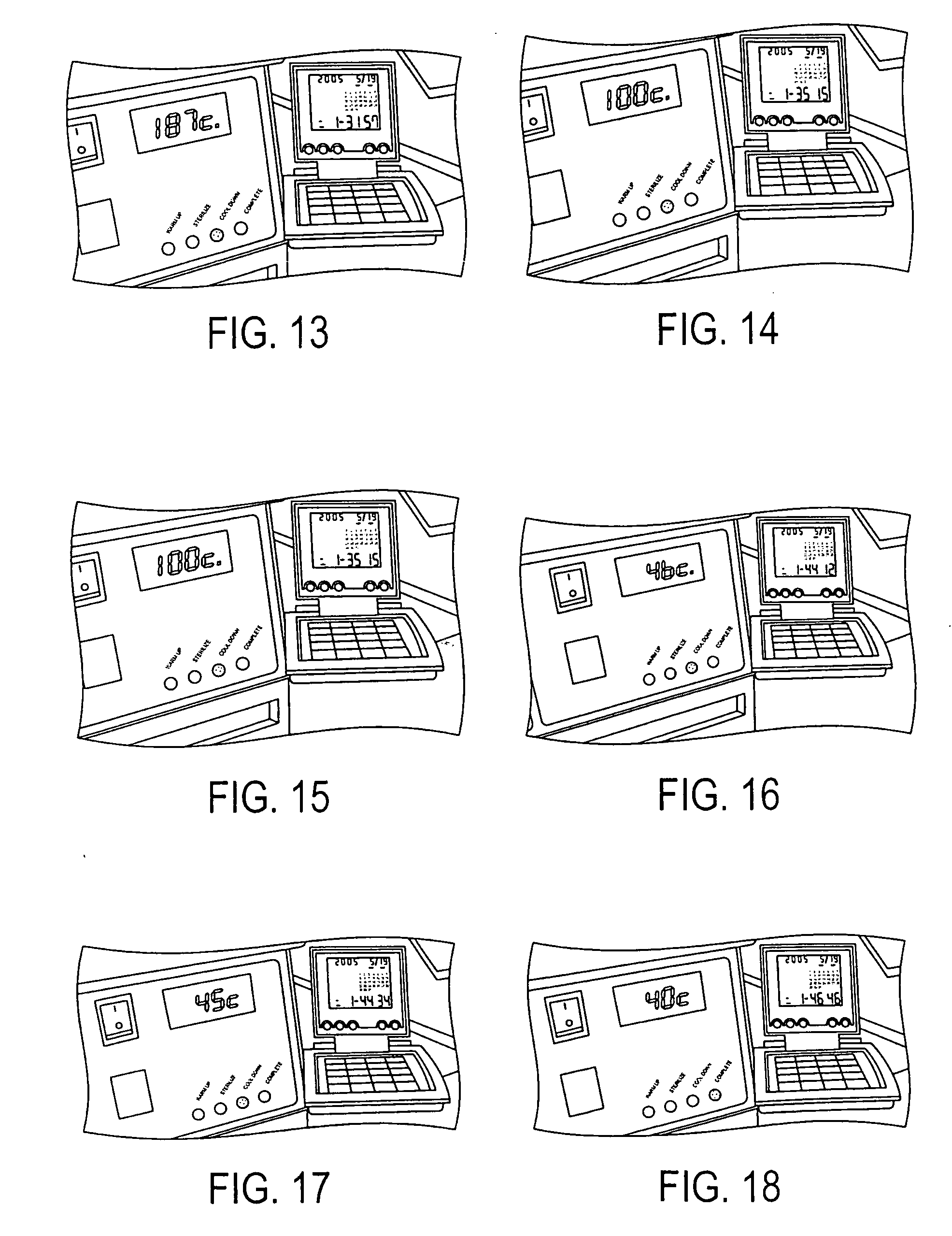
[0008] The present invention provides an improved dry air sterilization system and methods for sterilizing, for example, dental or surgical tools. Not including heat-up and cool down time, the system is adapted to sterilize in a short (e.g., three minute) cycle. The system may use a temperature monitored forced air cool down process. Filtered air may be used during cool down through the use of a replaceable HEPA filter that complies with ANSI/AAMI ST50: 2004. A safety door lock feature may be employed to lock the door when the

Problems solved by technology

One disadvantage suffered by all of these approaches with forced air cooling cycles is that cooling air is circulated through the sterilizer in such a way that it cools the sterilizing air heat source as well as the instruments and other objects being sterilized.

Method used


Image

  • Methods and apparatus for hot air sterilization of medical instruments
  • Methods and apparatus for hot air sterilization of medical instruments
  • Methods and apparatus for hot air sterilization of medical instruments

Examples


Embodiment Construction

[0037] While the present invention is illustrated and described in a preferred embodiment, the device may be produced in many different configurations, forms and materials. There is depicted in the drawings, and will herein be described in detail, a preferred embodiment of the invention, with the understanding that the present disclosure is to be considered as an exemplification of the principles of the invention and the associated functional specifications for its construction is not intended to limit the invention to the embodiment illustrated. Those skilled in the art will envision many other possible variations within the scope of the present invention.

[0038] Reference will now be made in detail to embodiments of the invention that are illustrated in the accompanying drawings. Wherever possible, same or similar reference numerals are used in the drawings and the description to refer to the same or like parts or steps. The drawings are in simplified form and are not to precise s...


PUM

PropertyMeasurementUnit
Temperatureaaaaaaaaaa
Timeaaaaaaaaaa
Timeaaaaaaaaaa

Abstract

A heat sterilizer sterilizes a load held in a sterilizing chamber at a predefined temperature over a shortened sterilization period by using predefined heating and cooling profiles. The sterilizer includes a temperature sensor coupled to a controller for sensing the temperature within the sterilizing chamber, where the controller is further adapted to monitor an output of the temperature sensor and maintain the temperature within the sterilizing chamber according to the predefined heating profile, the predefined temperature, or the predefined cooling profile, and where the controller is further adapted to specify an error condition if the controller fails to maintain the temperature within the sterilizing chamber according to the predefined heating profile, the predefined temperature, or the predefined cooling profile.

Description

BACKGROUND OF THE INVENTION [0001] 1. Field of the Invention [0002] The invention relates to hot air sterilization and, in particular, to self-contained hot air sterilizers with forced cooling to reduce sterilization cycle times. [0003] 2. Description of the Prior Art [0004] Certain medical practices such as small dental and / or orthodontic practices require the availability of large numbers of instruments during a day in the treatment of many patients. In order to reduce the total number of instruments needed to support such practices, sterilization turn around times must be as short as possible. Accordingly, sterilizers with rapid cooling cycles are valuable to such individual practices. [0005] Dry heat sterilization is increasingly becoming the method of choice for sterilizing medical instruments with carbide and carbon steel components. Such sterilization provides safety for all instruments which are chemically and moisture sensitive by introducing no foreign substances and by ef...

Claims


Application Information

Patent Timeline
IPC IPC(8): A61L2/24A61L2/04
CPCA61L2/04A61L2/06A61L2/24
Inventor FORSYTH, MICHAEL J.SMITH, GREGORY L.
Owner COLTENE WHALEDENT INC
Learn More