
Sensor device and stage device

a technology of sensor device and stage device, which is applied in the direction of angle measurement, photomechanical apparatus, instruments, etc., can solve the problems of large inability to accurately detect and inability to adjust the size of the whole stage device, so as to improve the detection accuracy and facilitate the detection of displacement and inclination angles.

Inactive Publication Date: 2007-02-22
SUMITOMO HEAVY IND LTD
View PDF11 Cites 29 Cited by
  • Summary
  • Abstract
  • Description
  • Claims
  • Application Information

AI Technical Summary

Benefits of technology

[0029] According to one aspect of the invention, there is provided a sensor device which is capable of detecting the state of five degrees of freedom of a movable stage using an easily manufacturable reference grating, and capable of improving the accuracy of detection.
[0030] According to one aspect of the invention, there is provided a stage device which is capable of detecting the state of five degrees of freedom of a movable stage using a sensor device having an easily manufacturable reference grating, and capable of improving the accuracy of detection.
[0037] According to the invention, it is possible to provide a sensor device and a stage device which can easily detect the displacements and inclination angles of a movable stage to a base by using a reference grating formed in an easily manufacturable configuration, and can improve the accuracy of detection.

Problems solved by technology

In a laser interferometer used for high precision instrumentation, in order to measure the position of the stage (positioning object) using a laser beam, there is a problem that the accuracy of a measurement value falls by a fluctuation of the air in the device in which the stage is placed.
For this reason, there is the problem in that the whole stage device is enlarged in size and the structure becomes complicated.
In rotating the stage around the Z-axis, there is a problem in that the reflected light from the stage separates from the light receiving unit of the interferometer and the X-Y direction position detection becomes impossible.
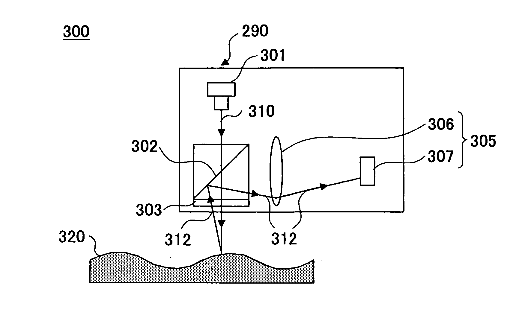
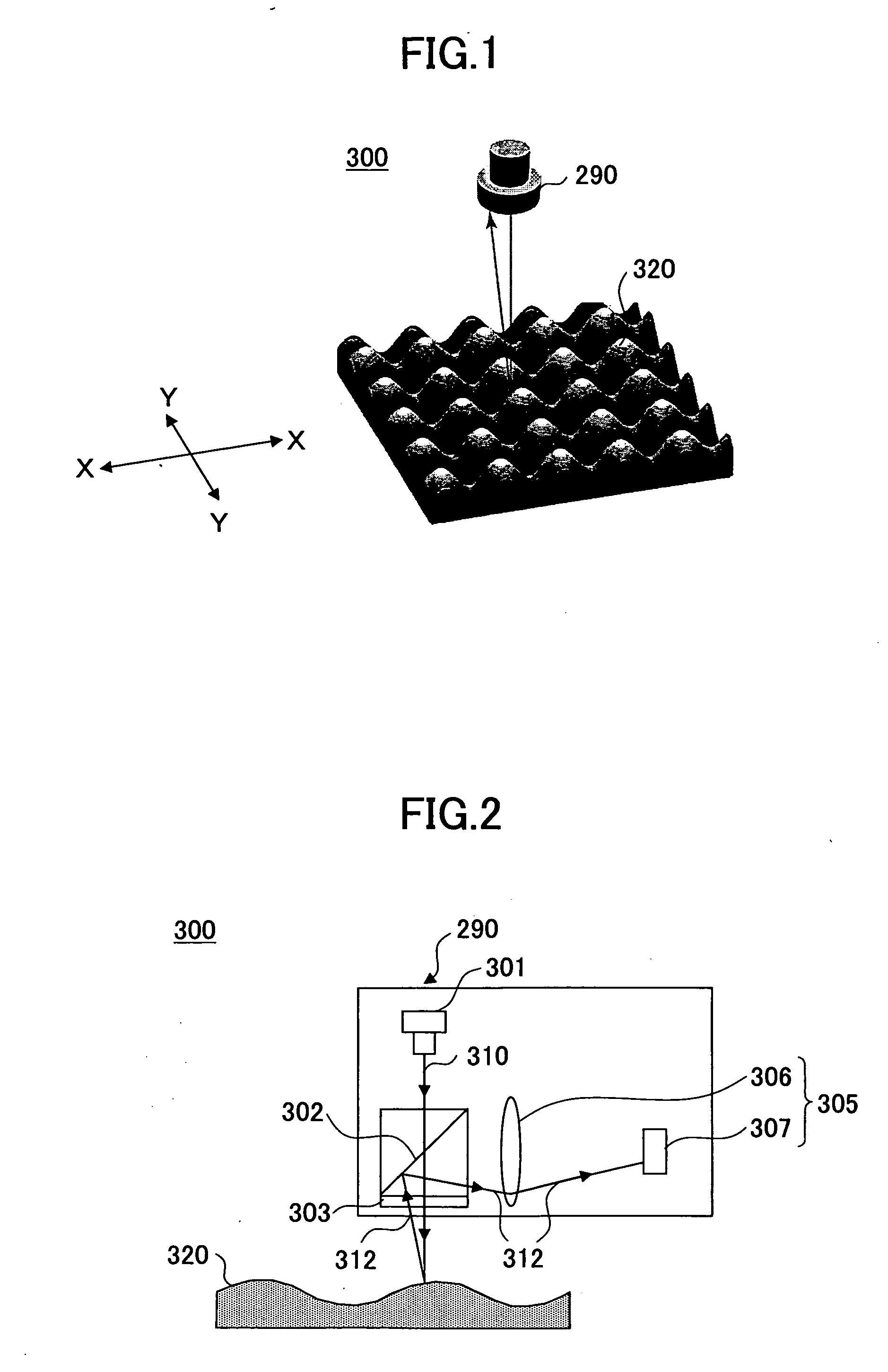
For this reason, the auto-collimation method requires the use of an expensive and complicated component, such as the autocollimator 305, and there is a problem that the cost of sensor device 300 becomes high.
In addition, the position detection is performed with high resolution, and there is a possibility that the geometrical-optics principle may not be satisfied due to interference and diffraction of the light as the period of the reference grating 320 and the multi-spot becomes short.
For this reason, there is a problem that it is difficult to detect with sufficient accuracy.
Therefore, there is a problem that the adjustment between these sensors is difficult to perform.
However, the amount of displacement of the stage in a different direction than the moving direction (for example, the up / down direction displacement and inclination angle around each axis of the stage) cannot be undetected by using the linear scale.
For this reason, there is a problem in that, if the stage is inclined, it is difficult to detect correctly the amount of the inclination of the stage and it is difficult to check in which direction the stage is inclined.

Method used


Image

  • Sensor device and stage device
  • Sensor device and stage device
  • Sensor device and stage device

Examples


Embodiment Construction

[0109] A description will be given of embodiments of the invention with reference to the accompanying drawings.

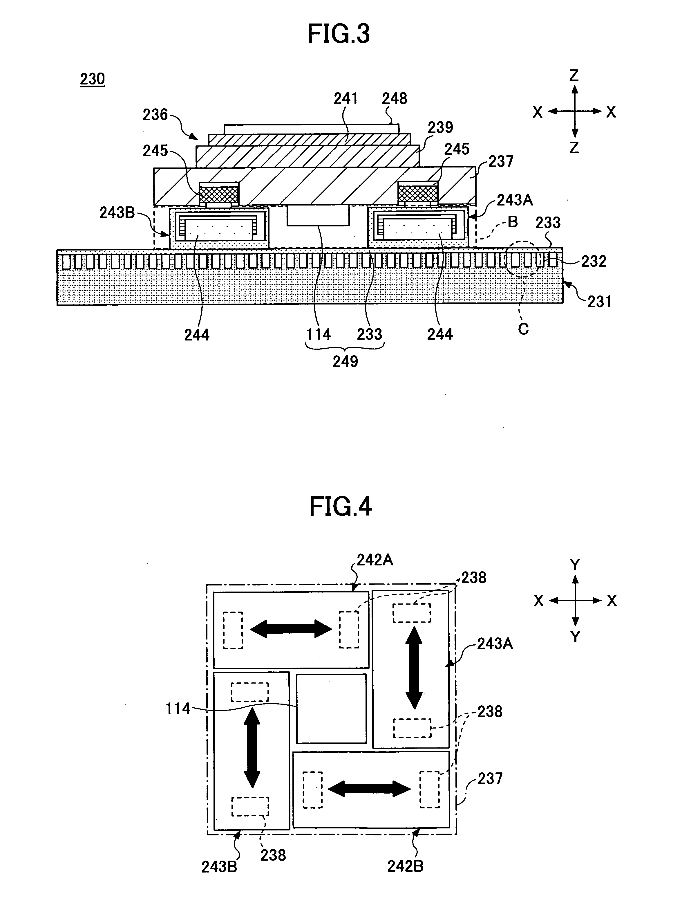
[0110] First, the stage device 230 in an embodiment of the invention will be explained with reference to FIG. 3 and FIG. 4.

[0111]FIG. 3 is a cross-sectional diagram of the stage device of the first embodiment, and FIG. 4 is a plan view of the structure of the stage device corresponding to the area B indicated in FIG. 3.

[0112] The stage device 230 is a stage device having a SAWYER motor drive part. The stage device 230 comprises a base 231, a stage 236, and a sensor device 249 as shown in FIG. 3. A plurality of convex parts 232 are formed on the surface of the base 231 at a predetermined pitch. This predetermined pitch is equivalent to the minimum unit of length by which a movable stage part 237 can be moved. The base 231 is made of a metal, such as iron. The stage 236 comprises a movable stage part 237, a fixed stage part 239, a chuck 241, X-direction actuators 242A and ...


PUM


Abstract

According to one aspect of the invention, there is provided a sensor device which is capable of detecting a state of a movable stage using an easily manufacturable reference grating and capable of improving the accuracy of detection. The sensor device comprises a reference grating which has a configuration that is varied periodically in a two-dimensional direction. A light source emits light to the reference grating. A spectral unit has a plurality of openings to convert the light emitted by the light source into a plurality of light beams through the plurality of openings. A detector unit has a photodetector to receive collectively reflected light beams reflected by the reference grating. The detector unit is provided to detect a state of a movable body relative to the reference grating based on a change of the reflected light beams received by the photodetector.

Description

CROSS-REFERENCE TO RELATED APPLICATION [0001] This application is a U.S. continuation application which is filed under 35 USC 111(a) and claims the benefit under 35 USC 120 and 365(c) of International Application No. PCT / JP2005 / 007481, filed on Apr. 19, 2005, the entire contents of which are hereby incorporated by reference. BACKGROUND OF THE INVENTION [0002] 1. Field of the Invention [0003] The present invention generally relates to a sensor device and a stage device, and more particularly to a sensor device which is adapted to detect the state of a stage which is moved with high accuracy, and a stage device in which the sensor device is provided. [0004] 2. Description of the Related Art [0005] Concerning ultra-precision machining devices and semiconductor devices which are the basis of information processing technology, the demand for high-accuracy positioning and high-speed processing of stage devices, used for these devices, is increasing. For example, for the stage device which...

Claims


Application Information

Patent Timeline
IPC IPC(8): G01B11/14G01B11/00G01D5/28G01D5/38G03F7/20H01L21/027H01L21/68
CPCG01D5/28G01D5/38G03F7/70758G03F7/70775G01D2205/90G03F7/70716
Inventor GAO, WEIKIYONO, SATOSHITOMITA, YOSHIYUKIHIRATA, TORUWATANABE, YOJIMAKINO, KENNICHI
Owner SUMITOMO HEAVY IND LTD
Learn More