
Micromechanical component

a micro-mechanical and component technology, applied in the direction of semiconductor devices, semiconductor/solid-state device details, electrical devices, etc., can solve the problems of uneven flow, uneven filling of the cavity, and disadvantageous thickness and shape of the sensor in the sheathing

Inactive Publication Date: 2007-02-22
ROBERT BOSCH GMBH
View PDF7 Cites 2 Cited by
  • Summary
  • Abstract
  • Description
  • Claims
  • Application Information

AI Technical Summary

Benefits of technology

[0007] The exemplary micromechanical component according to the present invention guides the flow of a molding compound around the component in such a way that the injection mold is filled uniformly. As a result, it is possible to package the component largely without gas inclusions.
[0008] An exemplary embodiment of the present invention provides that the micromechanical component has a micromechanical element having a cap, the surface of which is favorable for the material flow from the at least one preferred direction. Advantageously, such a surface favors laminar flows and prevents turbulence and consequent gas inclusions in the material flow.
[0012] Another exemplary embodiment of the present invention provides that the micromechanical component has a lead frame and the lead frame has at least one port for guiding the material flow. Advantageously, it is thus possible to fill a portion of the material flow into areas in the vicinity of the micromechanical component before gas inclusions are produced there by another portion of the material flow.

Problems solved by technology

The thickness and shape of the sensor prove to be disadvantageous in sheathing.
This results in an uneven flow and consequently an irregular filling of the cavity above and below the sensor element and to turbulence of the molding compound behind the sensor.

Method used


Image

  • Micromechanical component
  • Micromechanical component
  • Micromechanical component

Examples


Embodiment Construction

[0018] The invention will be elucidated in detail with reference to the embodiments described below.

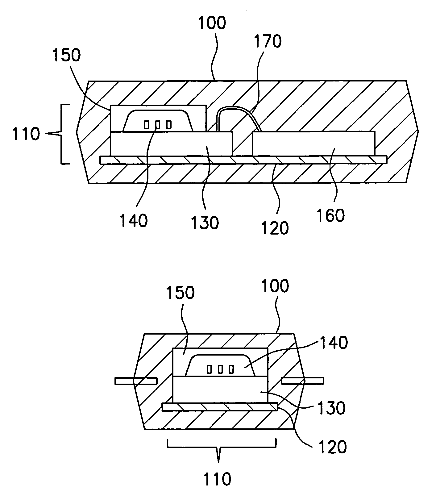
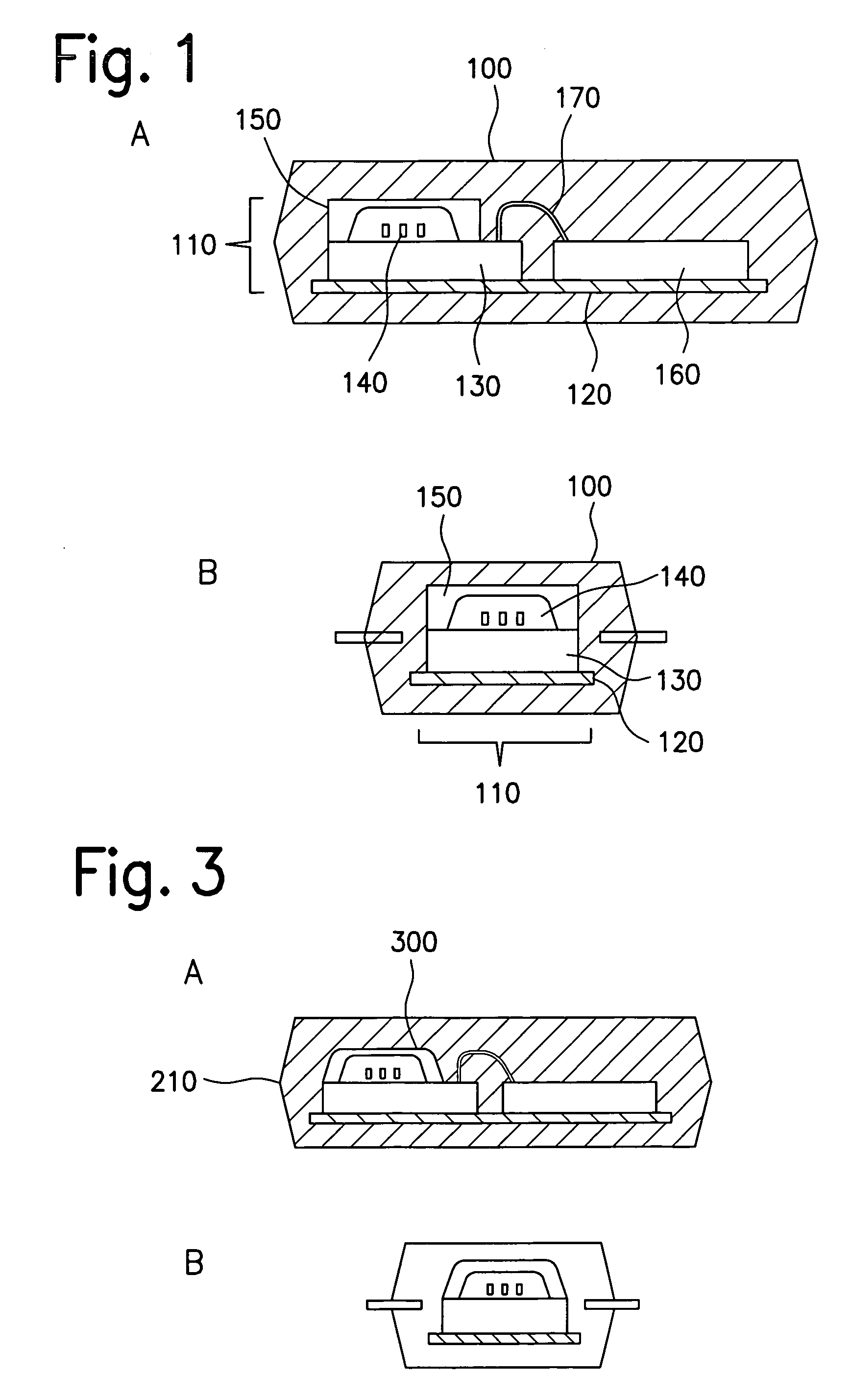
[0019]FIG. 1 shows the structure of a sheathed micromechanical sensor from the related art. First side view FIG. 1A shows an injection molded housing 100 having a component 110 within it. Component 110 includes a lead frame 120 having electronic and micromechanical elements mounted on it. In this example, a microelectronic circuit 160 and a micromechanical element 130 connected electrically by bonding wires 170 are situated on lead frame 120. Micromechanical element 130 has micromechanical functional elements 140 which are covered by a cap 150 placed over them. Second side view FIG. 1B shows injection molded housing 100, lead frame 120, micromechanical element 130 including its micromechanical functional elements 140 and cap 150 placed over them.

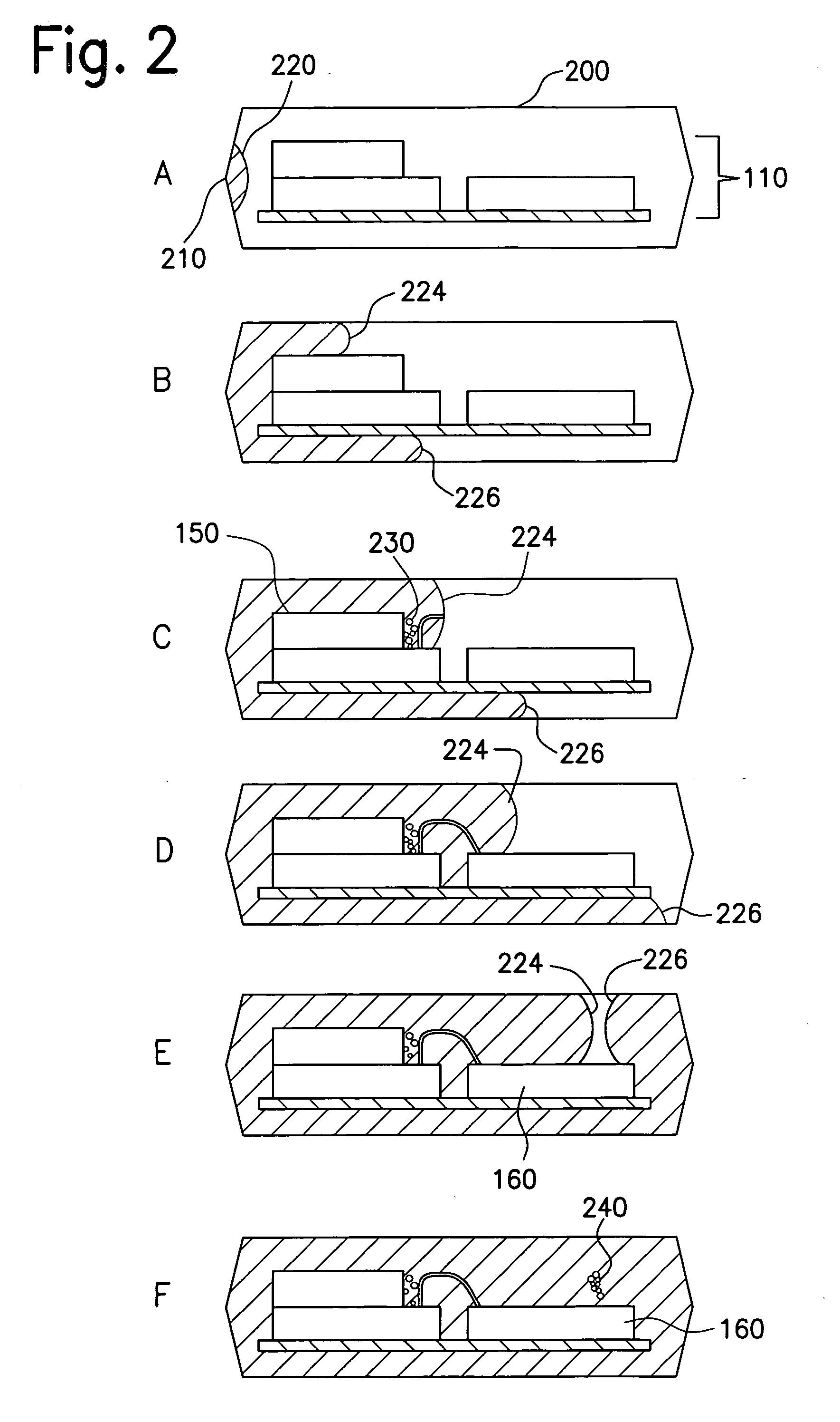
[0020] In subfigures A-F, FIG. 2 shows the filling behavior of the injection molding compound when a micromechanical sensor is packaged acc...


PUM


Abstract

A micromechanical component has a structure such that a material flow is guided from at least one preferred direction for the purpose of uniformly enveloping the micromechanical component.

Description

FIELD OF THE INVENTION [0001] The present invention relates to a micromechanical component having a structure such that a material flow is guided from at least one preferred direction for the purpose of uniformly enveloping the micromechanical component. BACKGROUND INFORMATION [0002] German patent application DE 195 37 814 A1 discusses the structure of a sensor-layer system and a method for hermetically packaging sensors in surface micromechanics. The manufacture of the sensor structure is based on available technological methods. Capping is accomplished using a separate silicon cap wafer which is structured using elaborate structuring processes such as KOH etching, for example. The sensor cap is applied to the sensor wafer on the wafer level using a glass solder. For this purpose, a wide bond frame is provided on the edge of each sensor chip to ensure adequate bonding and tightness of the cap. [0003] According to the related art, the sensor element is mounted on a lead frame, conta...

Claims


Application Information

Patent Timeline
Patent Type & Authority Applications(United States)
IPC IPC(8): H01L29/82B81C99/00
CPCB81C1/00333H01L21/565H01L23/16H01L2224/45144H01L2924/00H01L2224/48091H01L2224/48137H01L2924/00014
Inventor REICHENBACH, FRANKHAAG, FRIEDERKAELBERER, ARND
Owner ROBERT BOSCH GMBH
Learn More