
Method and system for controlling label peeling and rejecting bad labels in a label printer or applicator system

Inactive Publication Date: 2007-02-22
PRINTRONIX INCORPORATED
View PDF0 Cites 20 Cited by
  • Summary
  • Abstract
  • Description
  • Claims
  • Application Information

AI Technical Summary

Benefits of technology

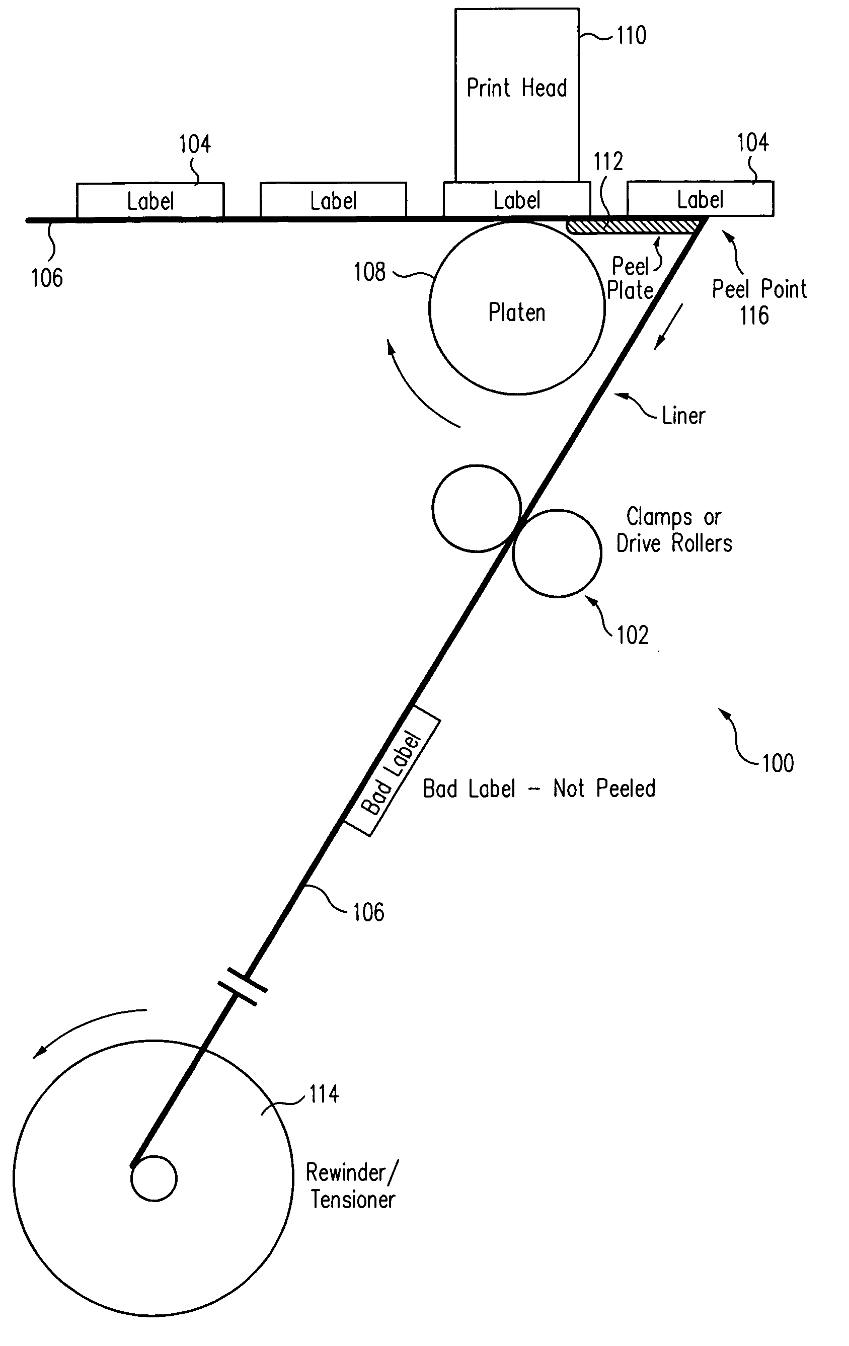
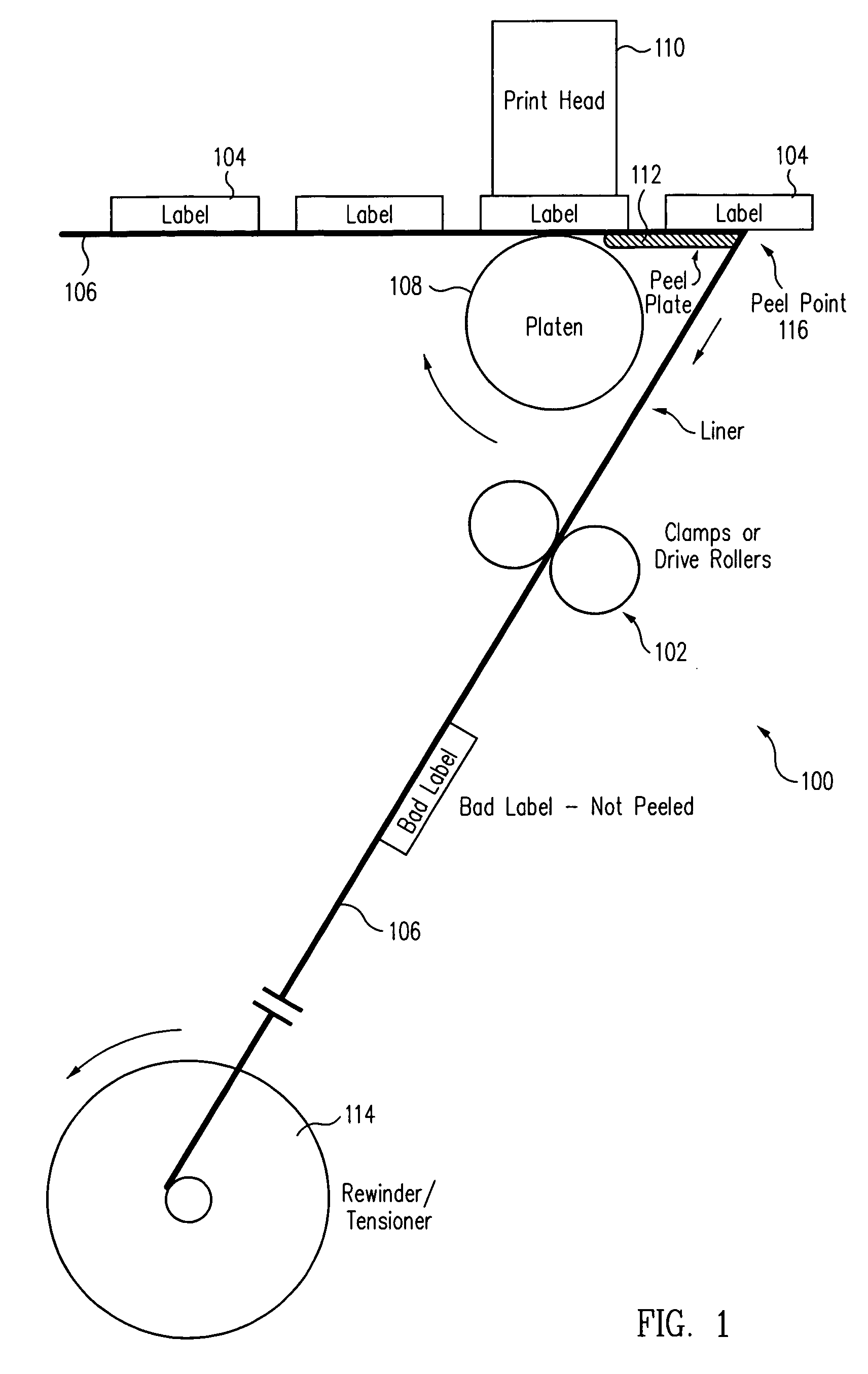
[0011] According to one aspect of the present invention, a tensioning mechanism is located close to a peel plate of a label applicator, where the tensioning mechanism relieves tension on a label liner near the peel plate when a bad label is detected. As a result, the bad label is not peeled and remains affixed to the liner, where it is wound up with the liner in a take-up reel or spool. The tensioning mechanism only relieves the tension along a small portion of the liner, which provides numerous advantages in a system for selectively peeling or not peeling labels.
[0012] In one embodiment, the tensioning mechanism is a clamp. The roll of labels is fed across a print head, such as an RFID encoder / reader, by a platen or other suitable mechanism. The peel plate is located past the platen. The labels are peeled off the liner as they move over the end of the peel plate, with tension being supplied by a take-up reel located at an angle of 90 degrees or greater from the path of the labels along the peel plate. When a bad label is detected, such as by the RFID encoder / reader or other label reader, the clamp closes to clamp the liner, resulting in tension being released between the clamp and the peel plate as the platen drives the label forward. This then prevents the bad label from being peeled from the liner. Once the front of the bad label has sufficiently passed the peel plate, the clamp is opened again, allowing the bad label to remain on the liner and travel to the take-up reel.
[0014] The present invention provides several advantages over conventional mechanisms, such as the ability to precisely control the peel or no-peel operation for very small labels, ease of design / manufacture using a simple clamping mechanism, conventional peel plates, and existing mechanisms to loosen the tension, e.g., the platen drive system, simpler operation since no need to decrease or increase the tension on the entire used liner, and very fast operation for engagement and disengagement of the peel / no peel process. The clamping device can be implemented in the form of drive rollers which start and stop and can also be used to create the peel tension on the liner. The drive rollers can also be used to increase tension by driving the liner toward the take-up reel or decrease tension by reversing its drive. The tensioning mechanism that creates the correct peel tension does not have to drop and regain tension for each bad label—an action that can create inconsistency in label peel tension.

Problems solved by technology

So, if a label is defective or bad, such as mis-printed information, unreadable tag or label, or improperly encoded tag, the bad label still is affixed to the package.
This renders the package identification worthless or worse yet, in error.
This is effective, but is a slow and imprecise operation.
It does not allow tightly controlling peel or no-peel of small labels spaced closely together on a liner.
When a bad label is detected, such as by the RFID encoder / reader or other label reader, the clamp closes to clamp the liner, resulting in tension being released between the clamp and the peel plate as the platen drives the label forward.

Method used


Image

  • Method and system for controlling label peeling and rejecting bad labels in a label printer or applicator system
  • Method and system for controlling label peeling and rejecting bad labels in a label printer or applicator system
  • Method and system for controlling label peeling and rejecting bad labels in a label printer or applicator system

Examples


Embodiment Construction

[0019] According to one aspect of the present invention, a tensioning mechanism in a label printer / applicator system is placed close to the peel plate so that tension or release of tension can be quickly and accurately applied, resulting in better control of whether a bad label is peeled or retained on a liner.

[0020]FIG. 1 shows a portion of a label printer or applicator system 100 using a tensioning mechanism 102 according to one embodiment of the present invention. System 100 includes labels 104 adhered to a web or liner 106. Labels 104 can be any suitable label, such as a bar code label or other label containing visually / optically readable data or an RFID label with an embedded RFID tag to store desired data. A platen 108 or other suitable roller moves labels 104 across a print head 110 for reading and / or writing to each label. In some embodiments, the labels are printed or encoded prior to reaching print head 110 so that print head 110 only reads the information printed on or s...


PUM

PropertyMeasurementUnit
Lengthaaaaaaaaaa
Speedaaaaaaaaaa
Tensionaaaaaaaaaa

Abstract

Instead of raising and lowering the tension in a full length of a liner with labels affixed thereto, the tension in a small portion of the liner is temporarily reduced, such as by clamping the liner between a tensioning device (usually a rewinder) and a peel point. The overall liner tensioning system is not affected. After the leading edge of a bad label is driven past the peel point, the tension is resumed, such as by releasing the clamping. The bad label then remains on the liner. This type of a mechanism allows rapid and precise control of tension at the peel point without having to control the overall tensioning system for the liner.

Description

CROSS REFERENCE TO RELATED APPLICATIONS [0001] The present invention claims priority to U.S. Provisional Application Ser. No. 60 / 709,496, filed Aug. 19, 2005, and which is incorporated by reference in its entirety.BACKGROUND [0002] 1. Field of Invention [0003] The present invention relates to label printers and applicators and, in particular, to mechanisms to handle labels in the printers and applicators. [0004] 2. Related Art [0005] Typically, labels contain identifying information for packages and products. The labels are affixed to the packages so that the package or contents thereof can be identified or tracked without opening the package. Traditional labels have visually or optically readable information printed on them, such as alphanumeric text or barcodes. More recently, labels have used RFID (Radio Frequency Identification) tags embedded therein to store and convey information. [0006] Regardless of the type of label, printers and applicators are used to apply the labels to ...

Claims


Application Information

Patent Timeline
IPC IPC(8): B29C63/00B32B41/00
CPCB65C9/1865B65C2009/0003Y10T156/1983B65C2009/405B65C2009/0093
Inventor CHAPMAN, THEODORE A.
Owner PRINTRONIX INCORPORATED
Learn More