
Veneered raised panel element and method of manufacturing thereof

a raised panel and raised panel technology, applied in the field of manufacturing of elements, can solve the problems of labor-intensive and expensive manufacturing process, lack of uniform color and grain pattern, door labor intensive and costly, etc., and achieve the effect of avoiding costly solid wood materials, uniform staining, and reducing the amount of wood stock taken

Inactive Publication Date: 2007-02-22
HOLLMAN JOE
View PDF22 Cites 14 Cited by
  • Summary
  • Abstract
  • Description
  • Claims
  • Application Information

AI Technical Summary

Benefits of technology

The present invention provides a raised panel door that is cost-effective, aesthetically pleasing, and structurally stable. The door comprises at least two vertically-oriented framing members, each having a cavity within the framing member along one of its elongated sides, and a center panel. Horizontally-oriented framing members are disposed between the vertically-oriented framing members to form a door frame. The members are assembled together to form the door using the cavity of the vertically-oriented framing members, the cope of the horizontally-oriented framing members, and glue. The door has edge banding applied to its outer edges. The invention avoids the use of costly solid wood materials and provides a less expensive, high quality raised panel door. The technical effects of the invention include improved structural stability and strength of the door, reduced warping and better uniformity of appearance, and improved aesthetical appearance.

Problems solved by technology

Although machines may be used to perform some of the processes used in forming raised panel door 10, many processes are performed by humans, resulting in a labor-intensive and expensive manufacturing process.
For many years, each of the five components of the raised panel door 10 was made of solid wood materials, which may be quite costly and often lack uniformity in color and grain patterns.
These doors are still labor intensive and costly, however, because the rails 12 and stiles 14 are still manufactured out of solid wood materials.
Manufacturing raised panel doors 10 with solid wood materials has resulted in disadvantages that affect the manufacturing process, the consumer, and the environment.
One disadvantage of raised panel doors 10 utilizing solid wood materials is the amount of wood that is required during manufacturing.
It is increasingly becoming more difficult to obtain solid stock without blemishes such as knots and which has consistent color.
These characteristics are undesirable to manufacturers because they compromise the high quality door desired by consumers.
The scarcity of wood stock possessing desirable characteristics is further exacerbated as this stock has become scarcer due to the stock being sold for veneers and at a higher price.
An entire manufacturing process may be needed to provide acceptable wood for the stiles and rails, and much of the original wood stock (e.g., 50-60%) may be wasted in the process.
Although the manufacturing of the center panel 16 out of a veneered substrate has alleviated some of the effects of wood shortages, other problems arise from the incorporation of different products into a single raised panel door 10.
Thirdly, the door 10 has a tendency to expand and contract more because of the solid wood materials used in the manufacturing of the stiles and rails.
Stapling also results in unsightly staple holes for the manufacturer to fill and evidence of the staple may still be seen in the finished product.
Warping of the solid wood pieces may also occur.
In addition, the ends of stiles 14 next to the cope of rails 12 exposes the cross grain of the wood, which does not match and is not as aesthetically pleasing as the wood on the side of the adjacent rails.
Also, the end grain generally allows a faster rate of moisture absorption than the edge grain, thereby increasing the risk of warping and instability.

Method used


Image

  • Veneered raised panel element and method of manufacturing thereof
  • Veneered raised panel element and method of manufacturing thereof
  • Veneered raised panel element and method of manufacturing thereof

Examples


Embodiment Construction

[0030] The making and using of the presently preferred embodiments are discussed in detail below. It should be appreciated, however, that the present invention provides many applicable inventive concepts that can be embodied in a wide variety of specific contexts. The specific embodiments discussed are merely illustrative of specific ways to make and use the invention, and do not limit the scope of the invention.

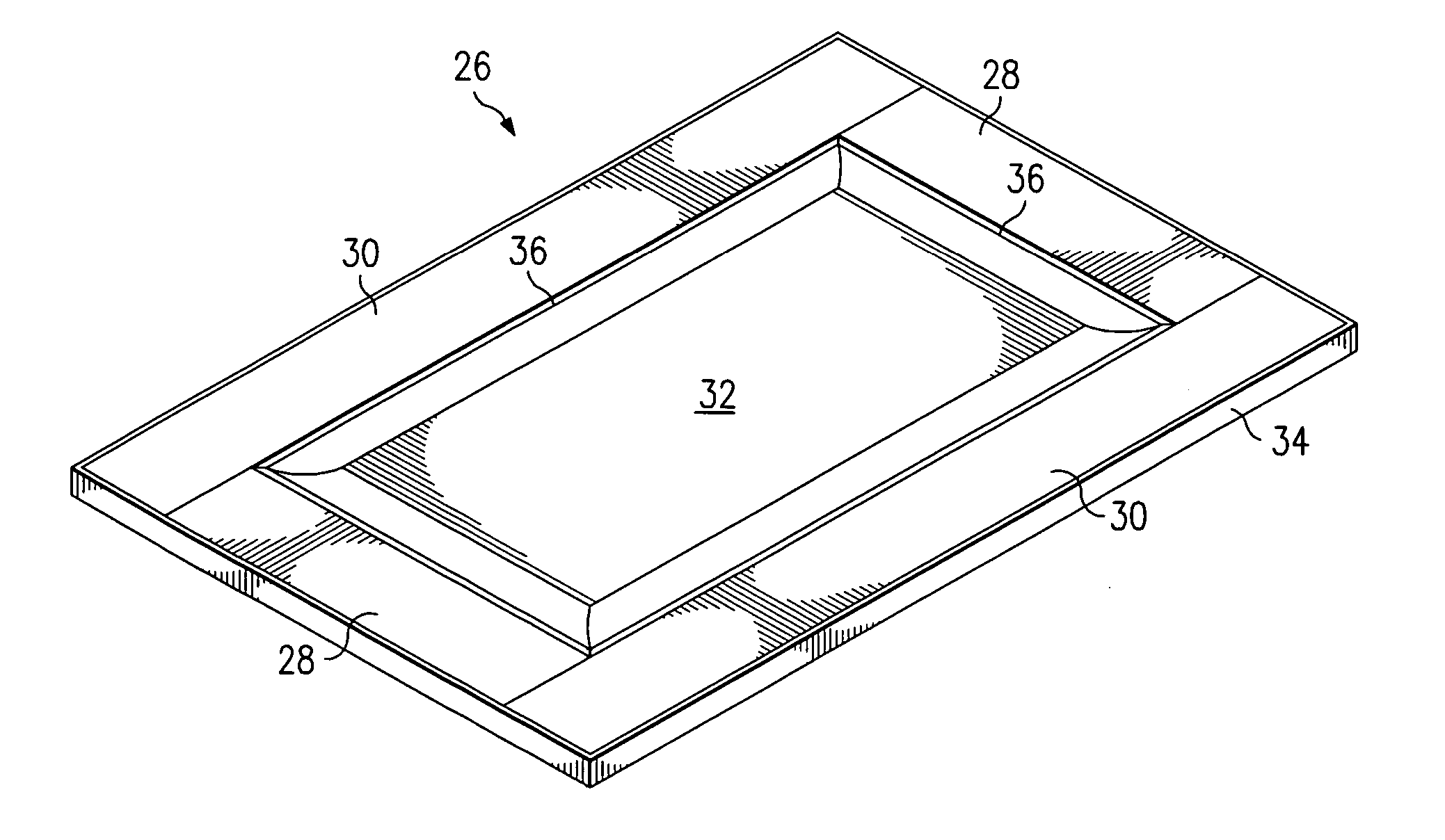
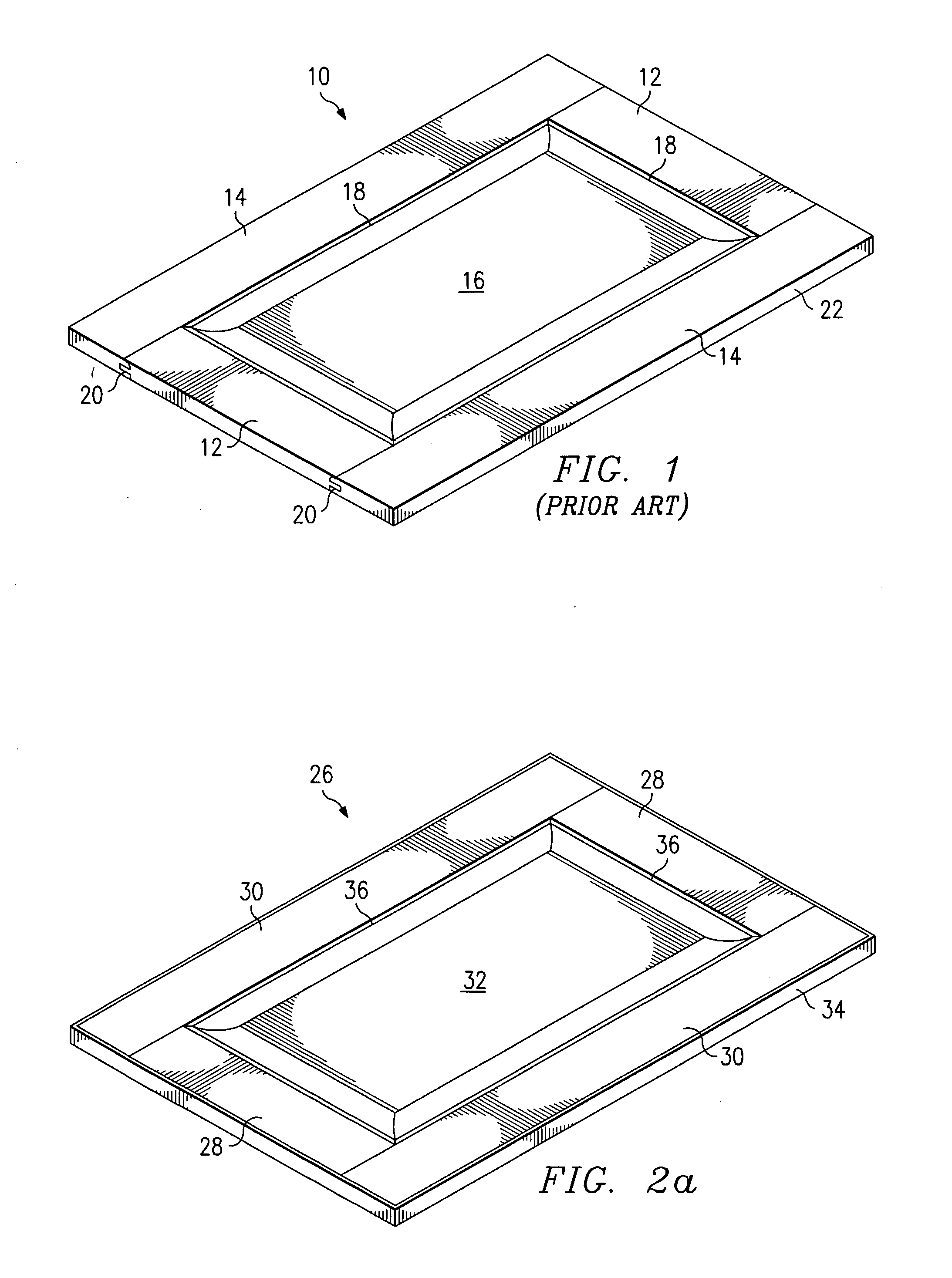
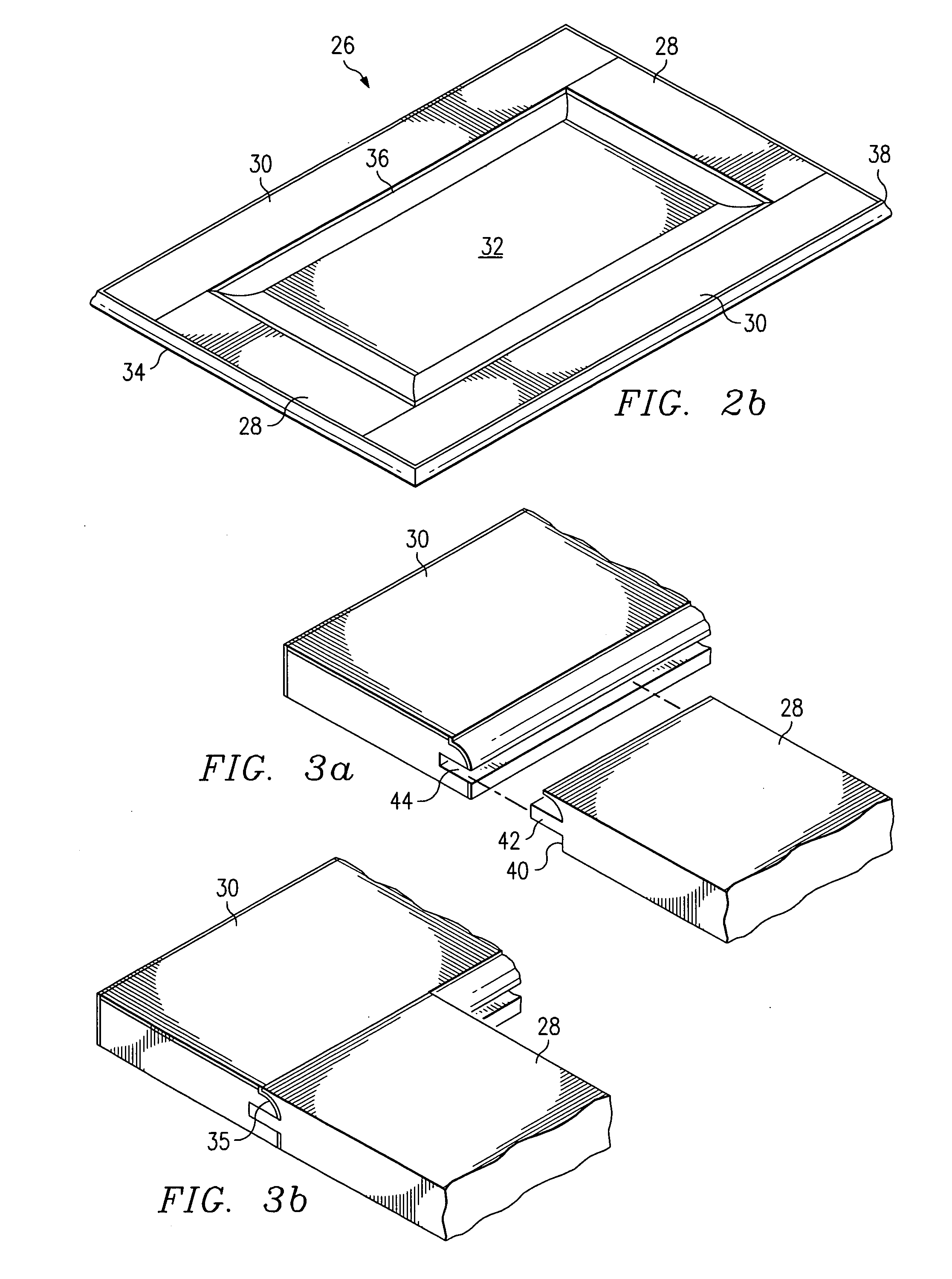
[0031] With reference now to FIGS. 2a and 2b, there are shown isometric views of preferred embodiment raised panel doors 26. The door 26 comprises horizontally-oriented members or rails 28, vertically-oriented members or stiles 30, a center panel 32, and edge banding 34. The rails 28, stiles 30, and center panel 32 are comprised of a wood veneer laid over a manufactured material such as pressed wood, medium density fiber board (MDF), particle board, chip board, or some other engineered core material. The rails 28 and stiles 30 each contain an inner edge 36 which may be a si...


PUM


Abstract

The present invention relates to veneered paneled elements such as doors. For example, a veneered raised panel door could include two vertically-oriented framing members (e.g., stiles) and two horizontally-oriented framing members (e.g., rails). These members are combined with a center panel to create a door frame. Each exposed edge of the door is layered with an edge banding. This edge banding (e.g., a wood or plastic veneer) covers any joints between the vertically-oriented and horizontally oriented framing members.

Description

[0001] This application is a divisional of U.S. patent application Ser. No. 10 / 451,960, filed on Jun. 27, 2003, which application claims priority to International Application No. PCT / US01 / 47909, filed on Dec. 12, 2001, which application claims priority to U.S. patent application Ser. No. 09 / 751,969, filed on Dec. 29, 2000, now U.S. Pat. No. 6,487,827, all of which applications are incorporated herein by reference.TECHNICAL FIELD [0002] The invention relates generally to the manufacture of elements such as doors and more particularly to a veneered raised panel element such as a door and method of manufacturing thereof. BACKGROUND [0003] Raised panel doors have been a part of the building and cabinet industries for many years. As shown in FIG. 1, a raised panel door 10 generally includes five components: two rails 12, two stiles 14, and a center panel 16. When the rails 12 and stiles 14 are assembled, the resulting structure is the outer frame 22 of door 10. The rails 12 form the hori...

Claims


Application Information

Patent Timeline
Patent Type & Authority Applications(United States)
IPC IPC(8): E06B3/70B27D5/00B27M3/00B27M3/18E04F13/10E06B3/74
CPCB27D5/003B27D5/006E06B3/74B27M3/18E04F13/10B27M3/0093
Inventor HOLLMAN, JOE
Owner HOLLMAN JOE
Learn More