
Low shading coefficient and low emissivity coatings and coated articles

a low emissivity coating and low shading coefficient technology, applied in coatings, natural mineral layered products, chemical instruments and processes, etc., can solve the problems of oblique incidence reflected color objectionable, and the efficacy of such an anti-reflection approach is restricted

Inactive Publication Date: 2007-02-15
PPG IND OHIO INC
View PDF12 Cites 30 Cited by
  • Summary
  • Abstract
  • Description
  • Claims
  • Application Information

AI Technical Summary

Benefits of technology

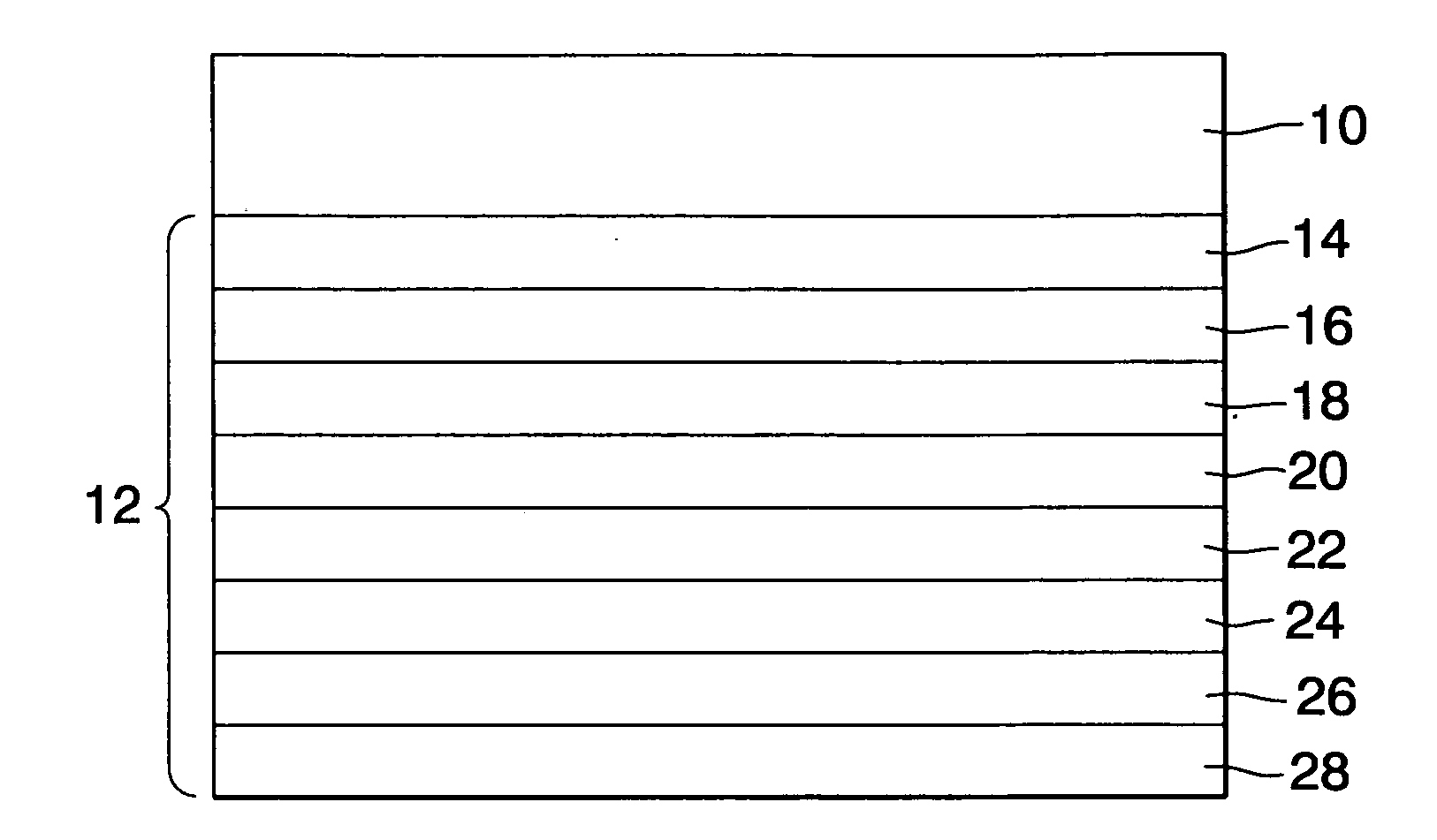
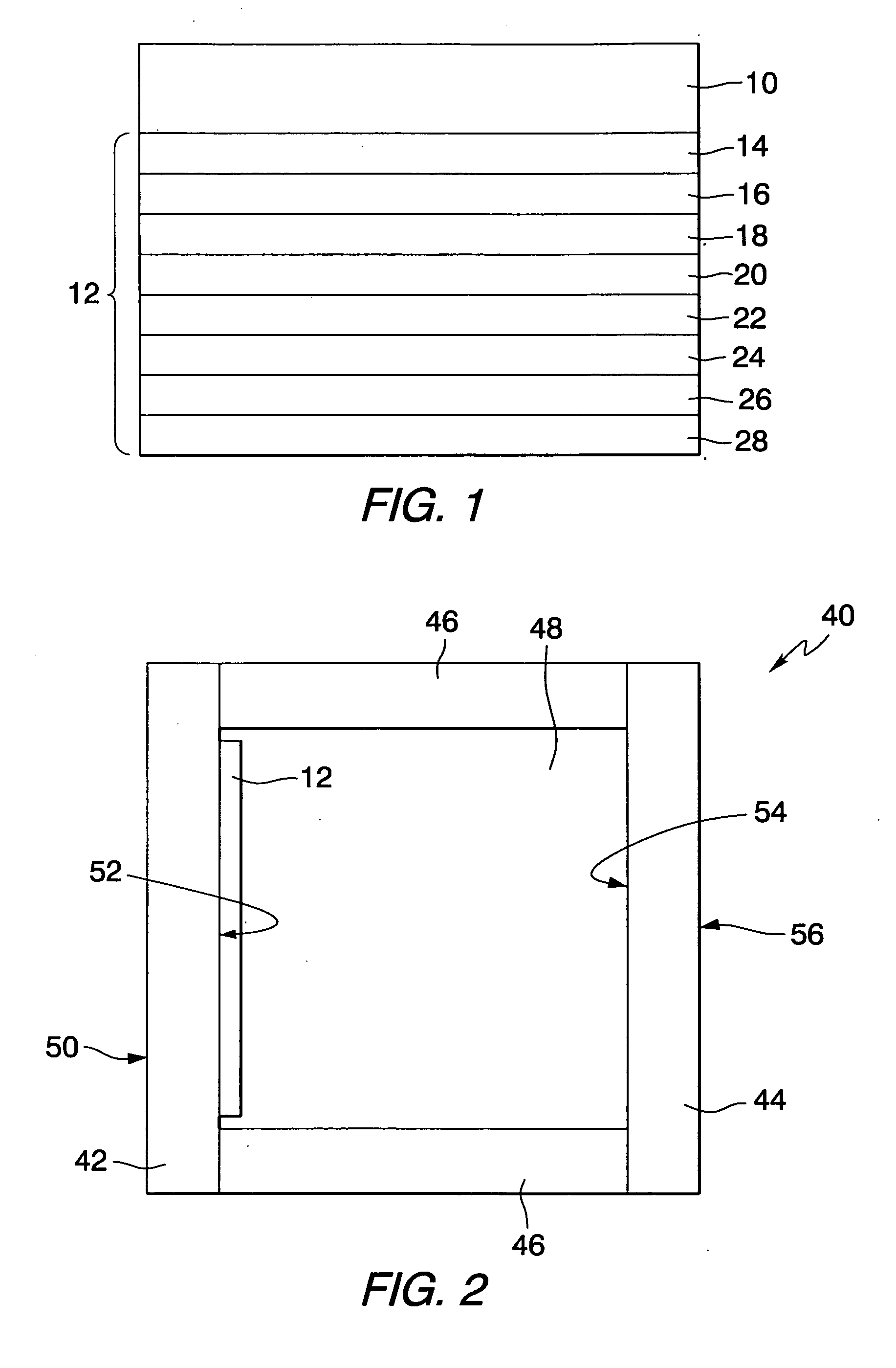
The present invention is a low-emissivity, low-shading coefficient, low-reflectance multi-layer coating for transparent or translucent substrates. The coating includes an antireflective layer and an infrared reflective layer, and has a high level of visible light transmittance, low shading coefficient, and low reflectance. The coated article has a neutral color and a blue or blue-gray interior color. The thickness of the layers in the coating is optimized to achieve the desired performance and aesthetics. The invention solves the challenge of producing a low-emissivity, solar-control coating with acceptable aesthetics for transparences in various applications.

Problems solved by technology

This is an important aesthetic issue concerning the variation of reflected and transmitted colors of the coated article with the angle of observation.
Although an improvement may be viewed at normal incidence, the reflected color viewed at oblique incidence may remain objectionable, or vice versa.
However, the optical characteristics of real thin film dielectric materials impose constraints on the efficacy of such an anti-reflection approach.

Method used


Image

  • Low shading coefficient and low emissivity coatings and coated articles
  • Low shading coefficient and low emissivity coatings and coated articles

Examples


examples

[0033] Coatings were prepared in accordance with the invention and analyzed for optical qualities. The coating layers were deposited at the specified thickness as shown in Table I on pieces of clear float glass of the thickness shown in Table I by MSVD for an IG unit. In the IG unit the coated glass was as reference number 44 and the coating as reference number 54 in FIG. 2. The structure of the coated samples is given in Table I, with the layer thickness given in Angstroms. In each sample, the first, second and third antireflective layers (AR layers) were multifilm zinc oxide and zinc stannate structures as described above. The numbers in Table I are for the total thickness of the specific layers, with each individual zinc oxide film in an AR layer being about 50 to 60 Angstroms thick. The first and second IR reflective layers (IR layers) were silver and the primer layers were titanium. The overcoat was titanium dioxide. The notation ND means that no data was taken.

TABLE IGlassth...


PUM

PropertyMeasurementUnit
visible light reflectanceaaaaaaaaaa
shading coefficientaaaaaaaaaa

Abstract

The present invention is directed to a low emissivity, low shading coefficient, low reflectance multi-layer coating and coated article having a visible light transmittance of greater than about 50%, preferably greater than about 55%, a shading coefficient of less than about 0.33 and en exterior reflectance of less than about 30%. The coated article, e.g. an IG unit, has a substrate with a first antireflective layer deposited over the substrate. A first infrared reflective layer is deposited over the first antireflective layer and a first primer layer is deposited over the first infrared reflective layer. A second antireflective layer is deposited over the first primer layer and a second infrared reflective layer is deposited over the second antireflective layer. A second primer layer is deposited over the second infrared reflective layer and a third antireflective layer is deposited over the second primer layer, such that the coated article has a transmittance greater than about 55%, a shading coefficient of less than about 0.33 and a reflectance of less than about 30%. A protective overcoat, e.g. an oxide or oxynitride of titanium or silicon, and / or solvent soluble organic film former may be deposited over the third antireflective layer.

Description

CROSS-REFERENCE TO RELATED APPLICATION [0001] This application claims the benefits of U.S. Provisional Application No. 60 / 167,386, filed Nov. 24, 1999, entitled “LOW SHADING COEFFICIENT AND LOW EMISSIVITY COATINGS AND COATED ARTICLES”, which is herein incorporated by reference.FIELD OF THE INVENTION [0002] This invention relates generally to heat-reflective and solar-control glazing materials such as multilayered coatings and to articles, e.g. windows or insulating glass units, incorporating such coatings and, more particularly, to solar-control metal oxide-containing coatings which may form solar-control articles having intermediate levels of luminous (visible light) transmittance, relatively low shading coefficient and emissivity, and acceptable levels of luminous (visible light) reflectance. DISCUSSION OF TECHNICAL CONSIDERATIONS [0003] In the design of buildings, architects are sometimes asked to incorporate large amounts of windows into the building design to increase the feeli...

Claims


Application Information

Patent Timeline
Patent Type & Authority Applications(United States)
IPC IPC(8): B32B17/06C03C17/36
CPCC03C17/36C03C17/3607C03C17/3618C03C17/3681C03C17/3642C03C17/3652C03C17/366C03C17/3639
Inventor MEDWICK, PAUL A.CRISS, RUSSELL C.ARBAB, MEHRANFINLEY, JAMES J.CRISS, DENVRA
Owner PPG IND OHIO INC
Learn More