Rotor of rotating electric machine and method of assembling rotor of rotating electric machine
a technology of rotating electric machines and rotors, which is applied in the direction of manufacturing stators/rotor bodies, magnetic circuit rotating parts, and shape/form/construction of magnetic circuits, etc., can solve the problems of affecting the performance of rotating electric machines, leaking magnetic flux through gaps, and difficulty in installing reinforcing members
- Summary
- Abstract
- Description
- Claims
- Application Information
AI Technical Summary
Benefits of technology
Problems solved by technology
Method used
Image
Examples
first embodiment
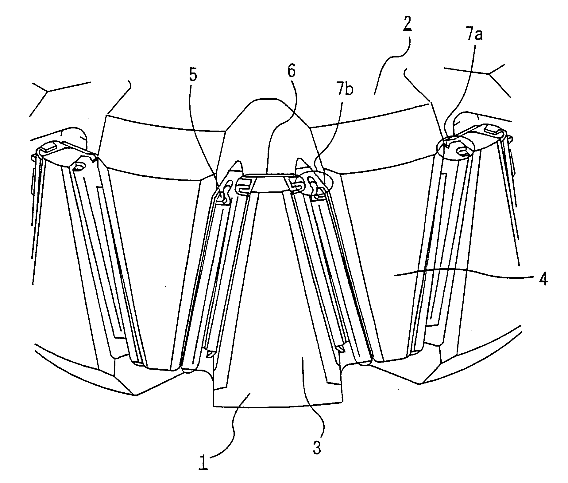
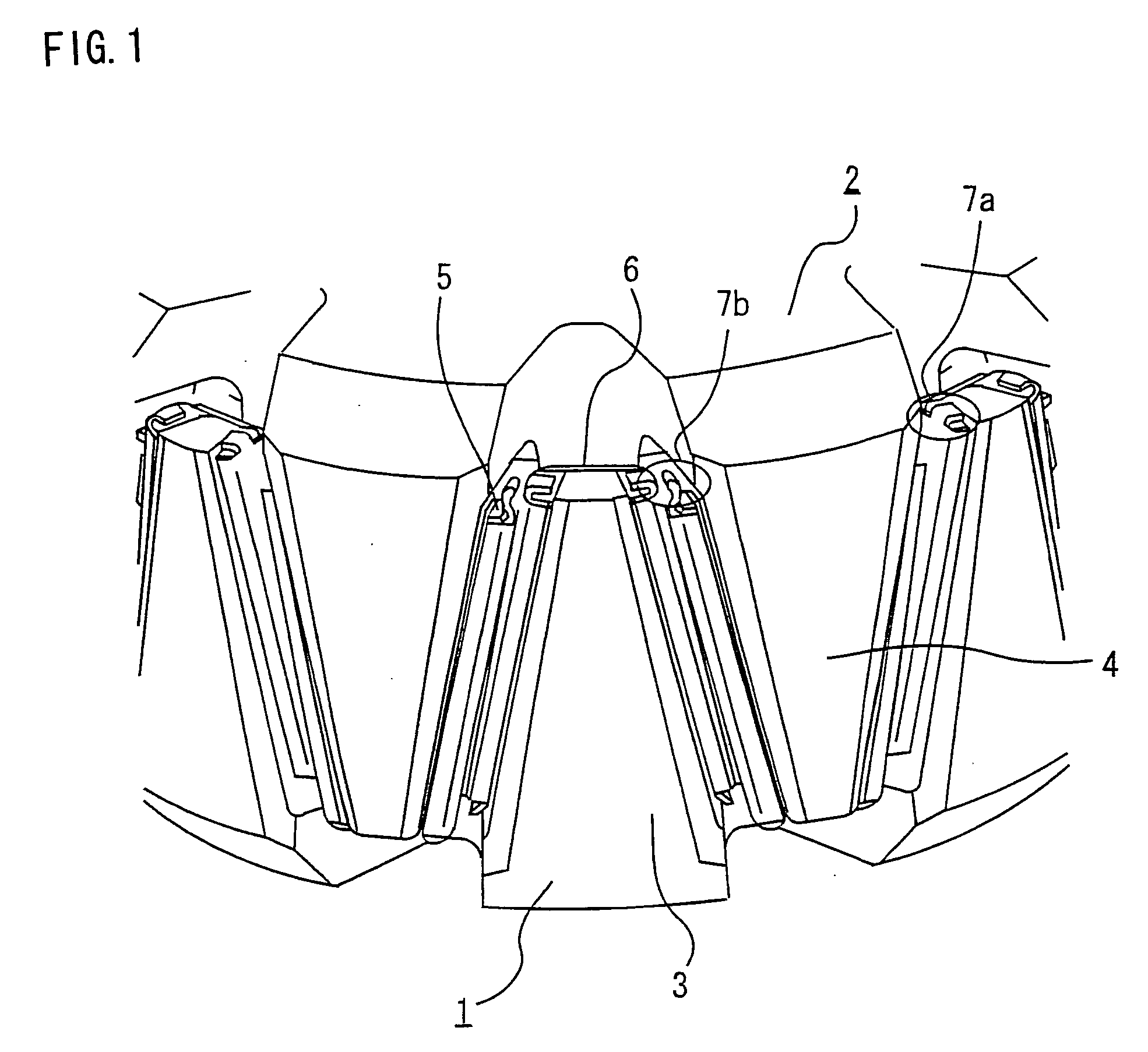
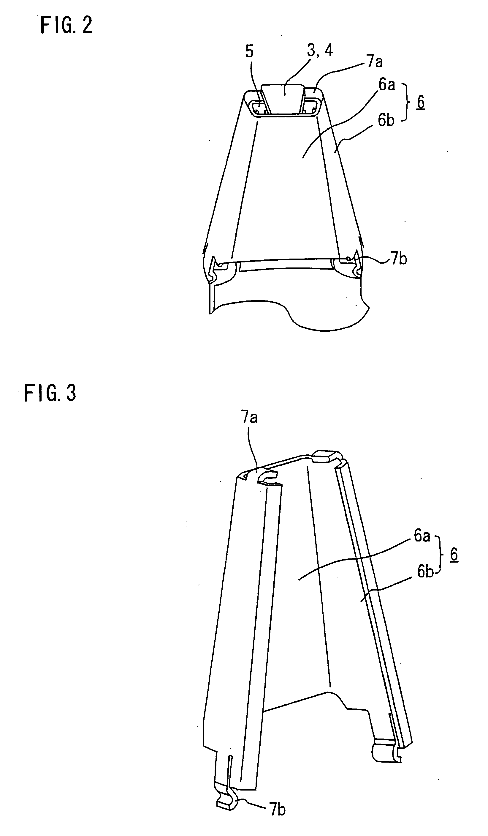
[0022]FIG. 1 is a perspective view showing a principal portion of a rotor of a rotating electric machine according to a first embodiment of the invention. Referring to FIG. 1, the rotor includes a pole core made up of a first pole core body 1 and a second pole core body 2, the pole core surrounding a rotor coil (not shown) for producing magnetic flux. The first and second pole core bodies 1, 2 respectively have claw-shaped magnetic poles 3 and 4 which extend alternately from opposite directions intermeshing one another, each of the claw-shaped magnetic poles 3, 4 narrowing from a basal end toward an extreme end. The rotor is provided with permanent magnets 5 which are disposed between facing side faces of the claw-shaped magnetic poles 3, 4 to reduce leakage of the magnetic flux through gaps between the side faces of the adjacent claw-shaped magnetic poles 3, 4. The rotor is further provided with magnet-mounting members 6 for fixedly holding the permanent magnets 5 against both side...
second embodiment
[0029]FIG. 5 is a perspective view showing the construction of a magnet-mounting member 6 according to a second embodiment of the invention. Like the magnet-mounting member 6 of the first embodiment, the magnet-mounting member 6 of this embodiment has a flat, platelike middle portion 6a which fits on an inclined inside surface of each claw-shaped magnetic pole 3 (4) and a pair of magnet-retaining portions 6b formed on both sides of the middle portion 6a for holding permanent magnets 5 against side faces of the claw-shaped magnetic pole 3 (4), the middle portion 6a and the magnet-retaining portions 6b together forming a generally C-shaped cross section as illustrated. Each of the magnet-retaining portions 6b on both sides of the magnet-mounting member 6 has an extreme-end hooking tab 10a at an extreme end and a basal-end hooking tab 10b at a basal end for retaining the permanent magnet 5 in position so that the permanent magnet 5 would not be displaced in either a basal-end or extrem...
PUM
| Property | Measurement | Unit |
|---|---|---|
| magnetic flux | aaaaa | aaaaa |
| displacement | aaaaa | aaaaa |
| magnetic | aaaaa | aaaaa |
Abstract
Description
Claims
Application Information
 - R&D
- Intellectual Property
- Life Sciences
- Materials
- Tech Scout
- Unparalleled Data Quality
- Higher Quality Content
- 60% Fewer Hallucinations
Browse by: Latest US Patents, China's latest patents, Technical Efficacy Thesaurus, Application Domain, Technology Topic, Popular Technical Reports.
© 2025 PatSnap. All rights reserved.Legal|Privacy policy|Modern Slavery Act Transparency Statement|Sitemap|About US| Contact US: help@patsnap.com


