
Ladle bottom

a technology of refractory articles and lids, applied in the direction of manufacturing tools, liquid transfer devices, furnaces, etc., can solve the problems of obstructing or preventing the discharge of contaminants from the outlet, and the drain block is a problem, so as to increase the fraction of liquid metals

Inactive Publication Date: 2007-02-08
VESUVIUS USA CORP
View PDF3 Cites 17 Cited by
  • Summary
  • Abstract
  • Description
  • Claims
  • Application Information

AI Technical Summary

Benefits of technology

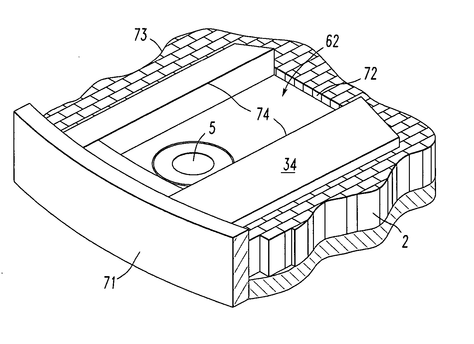
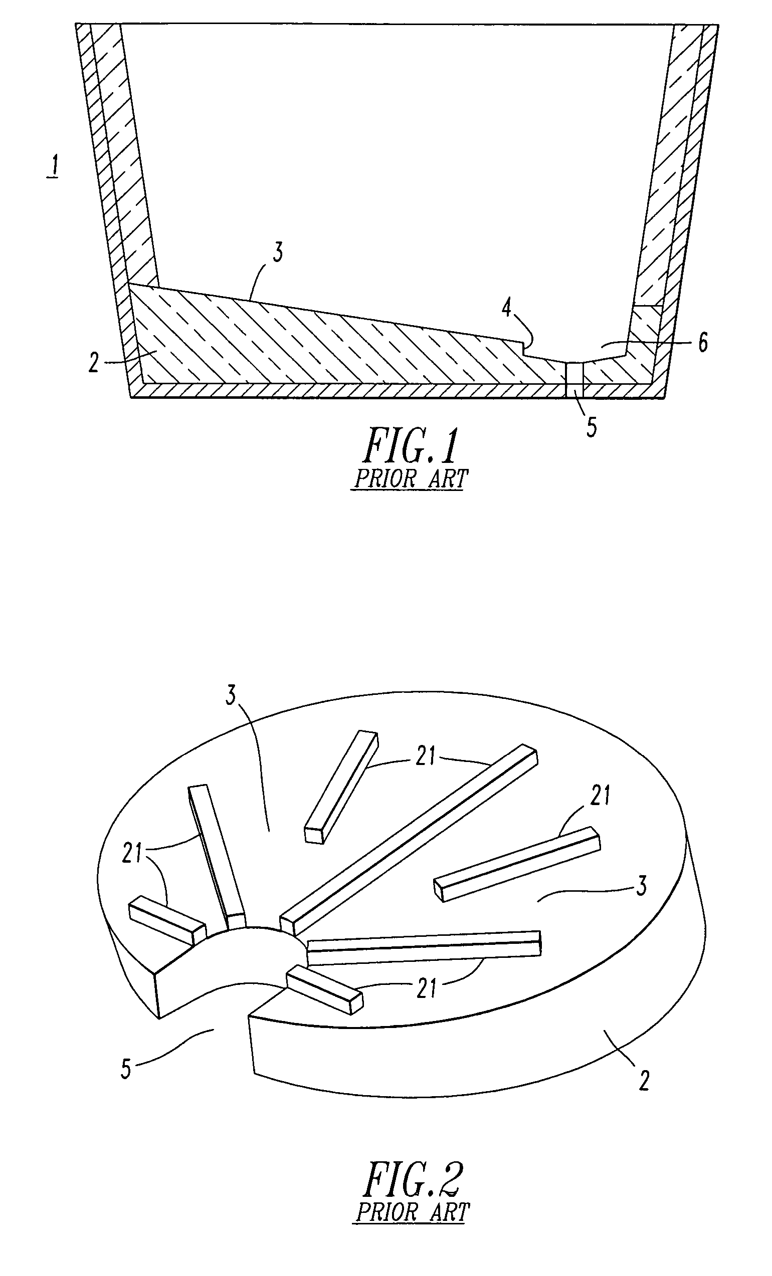
[0011] The present invention relates to a metallurgical ladle and more particularly to the bottom of the ladle having an outlet through which the molten metal can drain and a method to increase the fraction of liquid metal that can be drained from the ladle through the outlet without contamination by slag.
[0012] An object of the present invention is to increase the efficiency of the ladle draining operation, including reducing the amount of discarded metal, avoiding the premature flow of slag through the outlet, and reducing the contamination of slag in the molten metal effluent. The invention includes a ladle bottom drain block, which directs and controls the flow of liquid metal from the ladle so as to minimize the contamination of the liquid metal by slag. The drain block will comprise at least some portion of the total ladle bottom.
[0013] The drain block obstructs or impedes the discharge of contaminants from the outlet. Preferably, the invention retards entrainment of non-metallic materials, such as slag particles or globules, in the liquid metal exiting through the outlet until all or very nearly the entire liquid metal bath in the ladle has exited the ladle. Preferably, the drain block is a minor portion of the ladle bottom yet still controls the outflow while retarding the release of slag from the ladle.

Problems solved by technology

The drain block obstructs or impedes the discharge of contaminants from the outlet.

Method used


Image

  • Ladle bottom
  • Ladle bottom
  • Ladle bottom

Examples


example 1

[0046] A ladle drains at a maximum rate of 3 metric tons of liquid steel per minute. Liquid steel density is approximately 7 ton / m3 so the volumetric flow rate is 3 / 7 m3 / min or 0.007 m3 / sec. The minimum channel depth, Dmin, equals (0.007)2 / 3 or 0.037 m or 37 mm. The channel depth must be at least 37 mm for a 3 metric ton / minute throughput. The value chosen for D can be greater than 37 mm for this throughput, but cannot be less. The maximum channel width, Wmax, depends on the actual depth of the channel, D, and the value calculated for Dmin. If the value chosen for D is equal to Dmin, i.e. D=Dmin, then the maximum channel width, in accordance with equation (2), is 1.5 m. Similarly in accordance with equation (3), the minimum width of the channel, Wmin, is 0.5 m. Thus channel depth, W, must be between 0.5 and 1.5 m. If the value chosen for W is 1.0 m, then in accordance with equation (4), the minimum channel length, Lmin, must be at least equal to 0.5 times W, which means that the act...

example 2

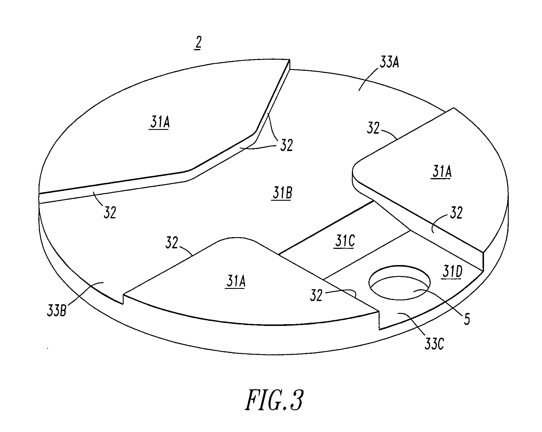
[0047] A ladle includes a bottom consisting essentially of a ladle block of the present invention. The ladle block includes three terraces separated by channels. One channel is an outlet channel and terminates in a well defining an outlet. The outlet channel has a width, length and depth corresponding to equations 1-4. Because the ladle block forms substantially the entire ladle bottom, the outlet channel length easily exceeds Lmin and the width and depth are chosen with convenient dimensions.


PUM

PropertyMeasurementUnit
Lengthaaaaaaaaaa
Flow rateaaaaaaaaaa
Widthaaaaaaaaaa

Abstract

The present invention relates to a ladle block for use in a bottom of a molten metal ladle. The ladle block reduces the amount of contaminants, particularly slag, exiting the ladle during casting operations. The ladle block includes a floor defining an outlet and sidewalls substantially orthogonal to the floor. The floor and sidewalls define a channel having dimensions of length, width and height. Channel dimensions are determined from the Froude number, which is based at least partially on the casting flow rate.

Description

[0001] This application is a continuation-in-part of U.S. Ser. No. 10 / 503,191, which is incorporated herein by reference.FIELD OF THE INVENTION [0002] This invention relates generally to refractory article and, more particularly, to a refractory shape used in the transfer of molten metal in a continuous casting operation. BACKGROUND [0003] A ladle is a vessel that is used to hold or transport a batch of liquid metal during metallurgical operations. The ladle lining includes a generally horizontal ladle bottom that is fashioned from refractory materials, such as blocks, bricks, or castable materials. The ladle bottom includes an outlet defining a bore that provides a generally vertical conduit for the outflow of liquid metal during casting. Typically, the outlet is encircled by or encompassed within a block called the nozzle block. The nozzle bock is set within and is surrounded by the remainder of the ladle bottom, which most commonly comprises bricks. To facilitate the casting proc...

Claims


Application Information

Patent Timeline
IPC IPC(8): C22B9/16B22D41/08B22D43/00
CPCB22D43/001B22D41/08
Inventor RICHAUD, JOHANHEASLIP, LAWRENCE J.DORRICOTT, JAMES D.
Owner VESUVIUS USA CORP
Learn More