One-way clutch

a one-way clutch and clutch technology, applied in the field of one-way clutches, can solve the problems of deteriorating the engagement function of the one-way clutch and increasing fuel consumption, and achieve the effects of reducing drag torque during idle rotation, preventing sliding wear between the inner race and the torque transmitting member, and ensuring the engagement ability

Inactive Publication Date: 2007-02-08
NSK WARNER
View PDF2 Cites 5 Cited by
  • Summary
  • Abstract
  • Description
  • Claims
  • Application Information

AI Technical Summary

Benefits of technology

[0007] Accordingly, an object of the present invention is to provide a one-way clutch in which an adequate engaging ability can be maintained even in a low temperature condition that viscosity of lubricating oil is increased, drag torque during an idle rotation can be reduced and sliding wear between an inner race and torque transmitting member can be prevented.
[0009] According to the present invention, the following advantages can be obtained.
[0010] Since the plurality of grooves extending substantially in the circumferential direction are formed in the outer peripheral track surface of the inner race, even in a low temperature condition that viscosity of lubricating oil is increased, an adequate engaging ability can be maintained. The reason is that, Due to the presence of the grooves of the inner race, an oil film between sprags or rollers and the inner race can be removed smoothly. Further, drag torque during an idle rotation can be reduced and sliding wear between the sprags or the rollers and the inner race can be prevented.

Problems solved by technology

In conventional one-way clutches, if viscosity of lubricating oil is increased in a low temperature condition (for example, −20° C. to −40° C. or below), when the one-way clutch is transferred from an idle rotation condition to an engaging condition, there is a danger of generating a problem in which normal or correct engagement cannot be achieved to cause continuous slipping, thereby deteriorating an engagement function of the one-way clutch.
In order to sole such a problem, although it can be considered that, by increasing a force of a spring for applying loads to sprags or rollers as the torque transmitting member in an engaging direction, surface pressure on the engaging surface is increased to facilitate the cutting of an oil film, if the spring force is increased, drag torque of the one-way clutch during the idle rotation is increased, with the result that, when the one-way clutch is used in a motor vehicle or the like, fuel consumption will be increased.

Method used


Image

  • One-way clutch
  • One-way clutch
  • One-way clutch

Examples


Embodiment Construction

[0016] Now, an embodiment of the present invention will be fully explained with reference to the accompanying drawings. Incidentally, in the drawings, the same or similar elements are designated by the same reference numerals. Further, it should be noted that the embodiment which will be described hereinbelow is merely exemplary and does not limit the present invention at all.

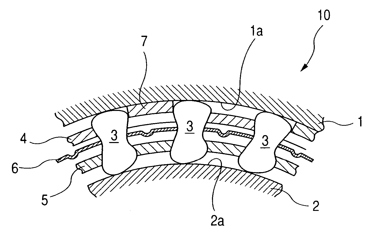
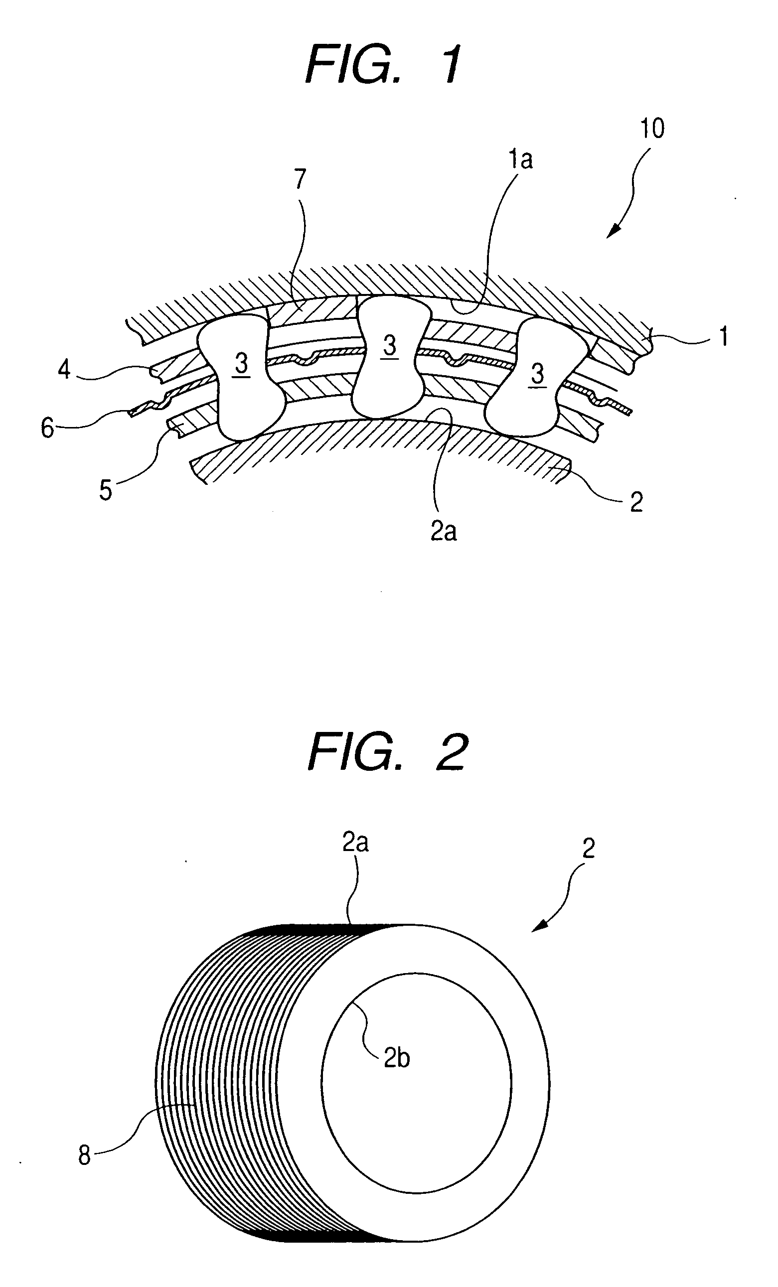
[0017]FIG. 1 is a partial radial sectional view of a one-way clutch 10 according to an embodiment of the present invention. The one-way clutch 10 comprises an outer race 1 having an inner peripheral track surface 1a, an inner race 2 arranged to be rotatable relative to the outer race 1 and having an outer peripheral track surface 2a, and sprags 3 as torque transmitting members for transmitting torque between the outer race 1 and the inner race 2.

[0018] The sprags 3 are held between an outer holder 4 and an inner holder 5 which are disposed between the outer race 1 and the inner race 2. Further, a ribbon sprin...


PUM


Abstract

The present invention provides a one-way clutch comprising an outer race, an inner race rotatable relative to the outer race and torque transmitting members for transmitting torque between the outer race and the inner race and wherein a plurality of grooves extending substantially in a circumferential direction are formed in an outer peripheral track surface of the inner race.

Description

BACKGROUND OF THE INVENTION [0001] 1. Field of the Invention [0002] The present invention relates to one-way clutches of sprag type and roller type used in vehicles or the like. More particularly, the present invention relates to a one-way clutch in which a circumferential groove is formed in outer peripheral surface of an inner race. [0003] 2. Related Background Art [0004] In general, a one-way clutch comprises an outer race, an inner race rotatable relative to the outer race, and torque transmitting members for transmitting torque between the outer race and the inner race. When the inner and outer races are rotated relative to each other, for example, toe torque transmitting members are engaged by an outer peripheral surface of the inner race, thereby transmitting the torque between the inner and outer races. [0005] In conventional one-way clutches, if viscosity of lubricating oil is increased in a low temperature condition (for example, −20° C. to −40° C. or below), when the one-...

Claims


Application Information

Patent Timeline
Patent Type & Authority Applications(United States)
IPC IPC(8): F16D41/069F16D13/60
CPCF16D41/07F16D2300/10F16D2300/06F16D2250/00
Inventor IWANO, AKIRASUZUKI, YUKIYOSHIMURAMATSU, KAZUHIKO
Owner NSK WARNER
Why Eureka
Try Eureka