Eureka AIR delivers breakthrough ideas for toughest innovation challenges, trusted by R&D personnel around the world.

Control circuit for a DC-to-DC switching converter, and the use thereof for maximizing the power delivered by a photovoltaic generator

a technology of dc-to-dc switching converter and control circuit, which is applied in the direction of light radiation electric generator, process and machine control, instruments, etc., can solve the problems of complex problems, inability to optimize the use of photovoltaic generator power, and excess power available, so as to improve the reliability and improve the overall effectiveness of the photovoltaic generator system

Inactive Publication Date: 2007-02-01
EUROPEAN SPACE AGENCY
View PDF2 Cites 207 Cited by
  • Summary
  • Abstract
  • Description
  • Claims
  • Application Information

AI Technical Summary

Benefits of technology

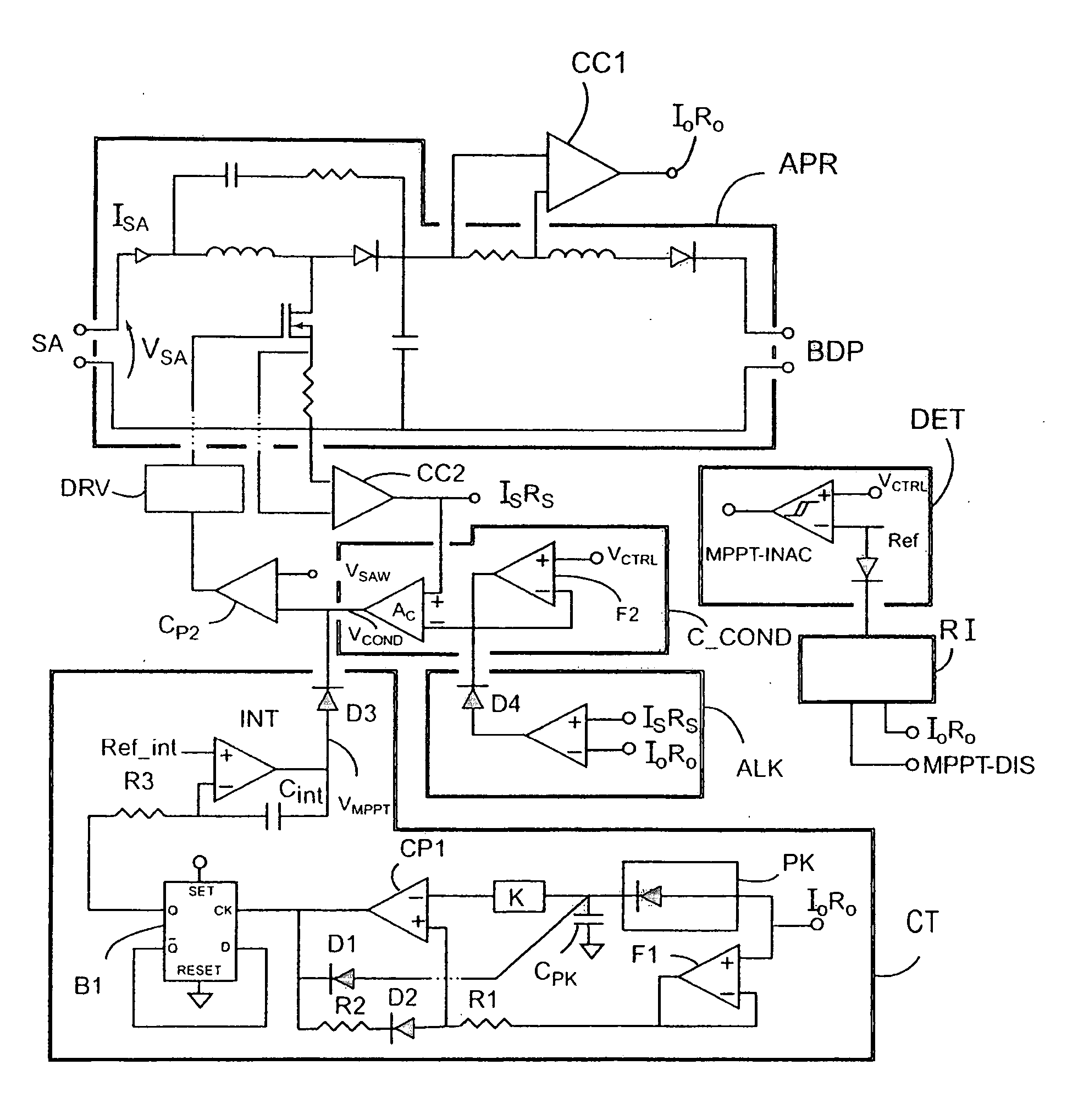
[0014] An object of the present invention is to mitigate at least one of the drawbacks of the prior art. In particular, the invention makes it possible to obtain an MPPT system which, while presenting good performance and good reliability, is sufficiently simple to enable a plurality of individual generators to be controlled independently, thereby improving the overall effectiveness of the photovoltaic generator system and relaxing requirements in terms of protecting and isolating said individual generators. In addition, the invention preferably uses a step-up switching converter as the converter power stage, thereby subsequently improving the reliability of the photovoltaic generator system.

Problems solved by technology

Thus, the lower the potential of the bus bar, indicative of high consumption by the equipment being powered and / or of a low level of charge in the batteries, the greater the number of individual generators that are connected to said bus bar.
Conversely, when the potential of the bus bar is high, generators are short-circuited, which means that there is excess power available.
The S3R regulator constitutes an excellent compromise between the requirements for effectiveness and for simplicity, however it does not make it possible to optimize the use of the power available from the photovoltaic generators.
However the problem is made much more complex by the fact that the characteristic curves vary very greatly with aging of the generators, and also depend strongly on temperature.
In conventional manner, MPPT systems use microprocessor-based controllers, but that is generally not desirable in space applications, in particular for reasons of reliability.
That is why analog MPPT controllers have been developed in the past, but until now none of them has given complete satisfaction.
Nevertheless, circuit complexity remains excessive for providing independent control of a large number of individual generators.
Thus, a plurality of solar arrays need to be connected in parallel and controlled together; this limits the effectiveness of the system and makes it necessary to use protection and isolation systems in order to avoid faults propagating.
Such a system presents the drawback of being synchronous (the sample-and-hold circuit is driven by a clock), thereby limiting its performance.
Good tracking of the optimum operating point can be obtained only by using slow oscillations around said optimum point, but that implies a long acquisition time in order to come close thereto.
That presents three major drawbacks: firstly, it is necessary to use high voltage solar generators (operating at several tens of volts (V) and up to more than 100 V), thus running a major risk of failure due to electric arcs forming in operation: secondly, a buck switching converter includes a controlled switch (typically a metal oxide on silicon field effect transistor (MOSFET)) connected in series with each generator; as a result, in the event of the switch failing, the generator is permanently isolated from the power supply bus bar; and thirdly, when the switch of a buck switching converter is constituted by a MOSFET, the MOSFET must be controlled by a floating driver circuit, thereby increasing the number of electronic components that are needed.

Method used


Image

  • Control circuit for a DC-to-DC switching converter, and the use thereof for maximizing the power delivered by a photovoltaic generator
  • Control circuit for a DC-to-DC switching converter, and the use thereof for maximizing the power delivered by a photovoltaic generator
  • Control circuit for a DC-to-DC switching converter, and the use thereof for maximizing the power delivered by a photovoltaic generator

Examples


Embodiment Construction

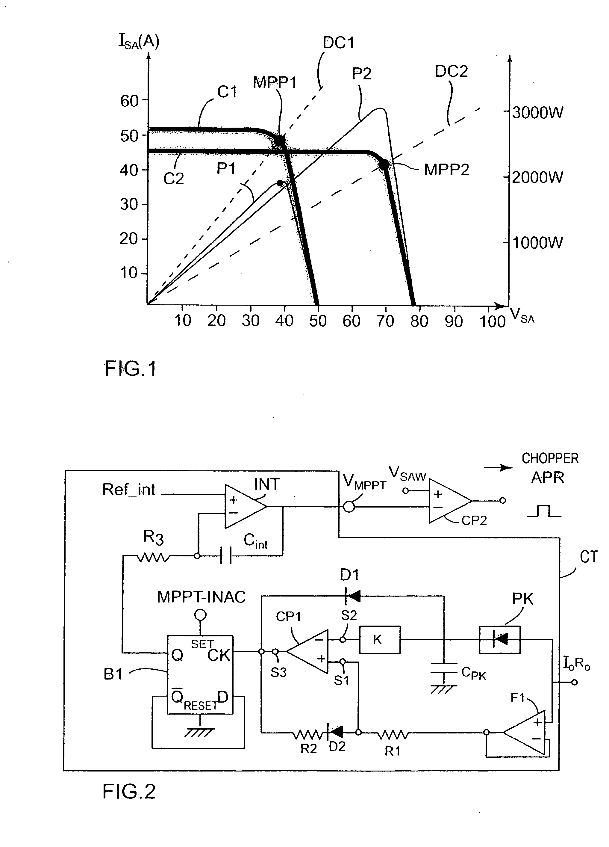
[0054]FIG. 1 shows examples of characteristic curves for photovoltaic generators. More precisely, the thick-lined curves C1 and C2 represent the relationship between the voltage VSA and the output current I for a generator at respective temperatures of 45° C. and of −90° C. At both temperatures, the characteristic curves present a first region of approximately constant current followed by a second region of approximately constant voltage in which the current drops off rapidly to zero for a small increase in voltage. The power generated is given by the relationship PSA=ISA(VSA)·VSA, and is represented by the fine-lined curves P1 and P2. The optimum operating point MPP1, MPP2 corresponds to generating maximum power and is situated in the region of the inflexion in the characteristic curves C1, C2: it is of interest to observe that these points correspond neither to maximum current nor to maximum voltage. The reciprocals of the slopes of the load lines CT1 and CT2 passing through the o...


PUM


Abstract

A control circuit for a switching DC / DC Converter comprising: an input for an indicator signal indicative of an output current level from said converter; a peak detector for detecting and storing a maximum value of said indicator signal; a comparator element for comparing an instantaneous value of said indicator signal with said stored maximum value, and for generating a switching signal when said instantaneous value becomes less than a predetermined fraction of said stored value; reinitializer means for reinitializing said peak detector in response to said switching signal; and means for generating a control signal that switches between a state in which it increases over time and a state in which it decreases over time in response to said switching signal. A control module for photovoltaic generator, the module including such a control circuit, and a photovoltaic generator system comprising a plurality of such modules, each controlling a respective photovoltaic generator.

Description

[0001] The invention relates to a control circuit for a DC-to-DC switching converter, and to its application to controlling a photovoltaic generator. The invention is intended mainly but not exclusively for space applications. BACKGROUND OF THE INVENTION [0002] Satellites and space probes generally include photovoltaic generators for powering on-board equipment and for charging batteries that deliver power during periods of eclipse. The photovoltaic generators, the batteries, and the various items of equipment that need to be powered are connected to one another by a power supply bus bar that presents a potential that needs to be kept within a predetermined range. Regulators are provided for controlling the magnitude of the currents delivered by said photovoltaic generators, in particular as a function of the potential of said power supply bus bar. [0003] The regulator in the most widespread use is the sequential switching shunt regulator (S3R or S3R) as developed by the European Sp...

Claims


Application Information

Patent Timeline
IPC IPC(8): G05F1/00H02N6/00
CPCY02E10/58G05F1/67Y02E10/56Y10S323/906
Inventor BOLDO, PABLO RUEDA
Owner EUROPEAN SPACE AGENCY
Why Eureka
Eureka Blog
Learn More