
Resonant charge power supply topology for high pulse rate pulsed power systems

a power supply and pulsed technology, applied in the field of electric power systems, can solve problems such as the regulation of the maximum voltage across the capacitor, and achieve the effect of high pulse repetition rate and high energy pulses

Inactive Publication Date: 2007-01-25
GENERAL ATOMICS ELECTRONICS SYST
View PDF15 Cites 16 Cited by
  • Summary
  • Abstract
  • Description
  • Claims
  • Application Information

AI Technical Summary

Benefits of technology

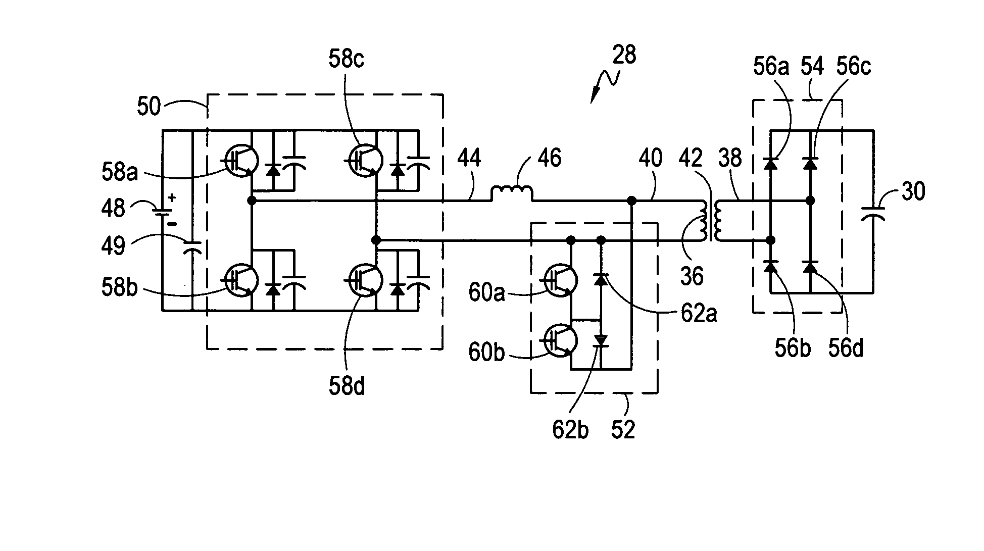
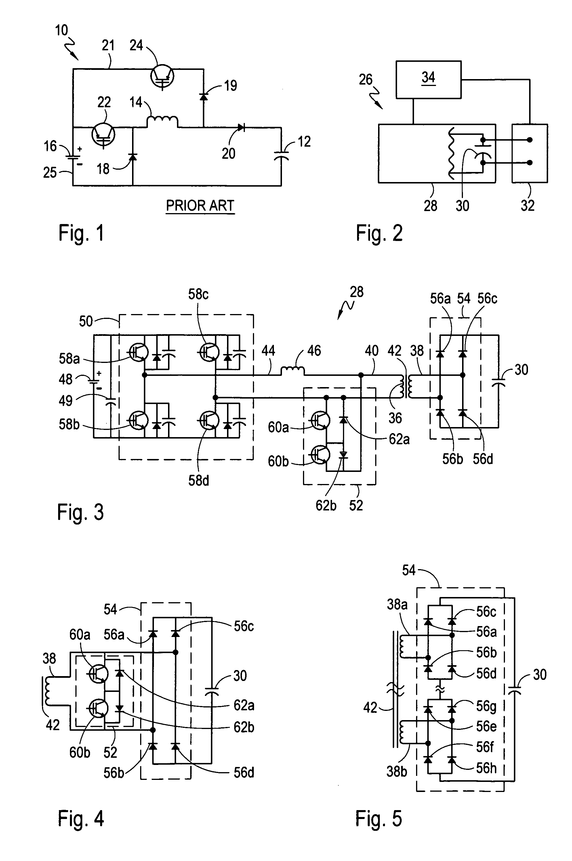
[0008] The present invention is directed to a power supply system that charges a capacitor with relatively high energy pulses, at a relatively high pulse repetition rate. The system works in conjunction with a load (e.g. UAV laser lamps) that is switchably connected to the capacitor. At the end of each pulse, the load is connected (i.e. switched) across the capacitor. This then discharges the capacitor and energizes the load.

Problems solved by technology

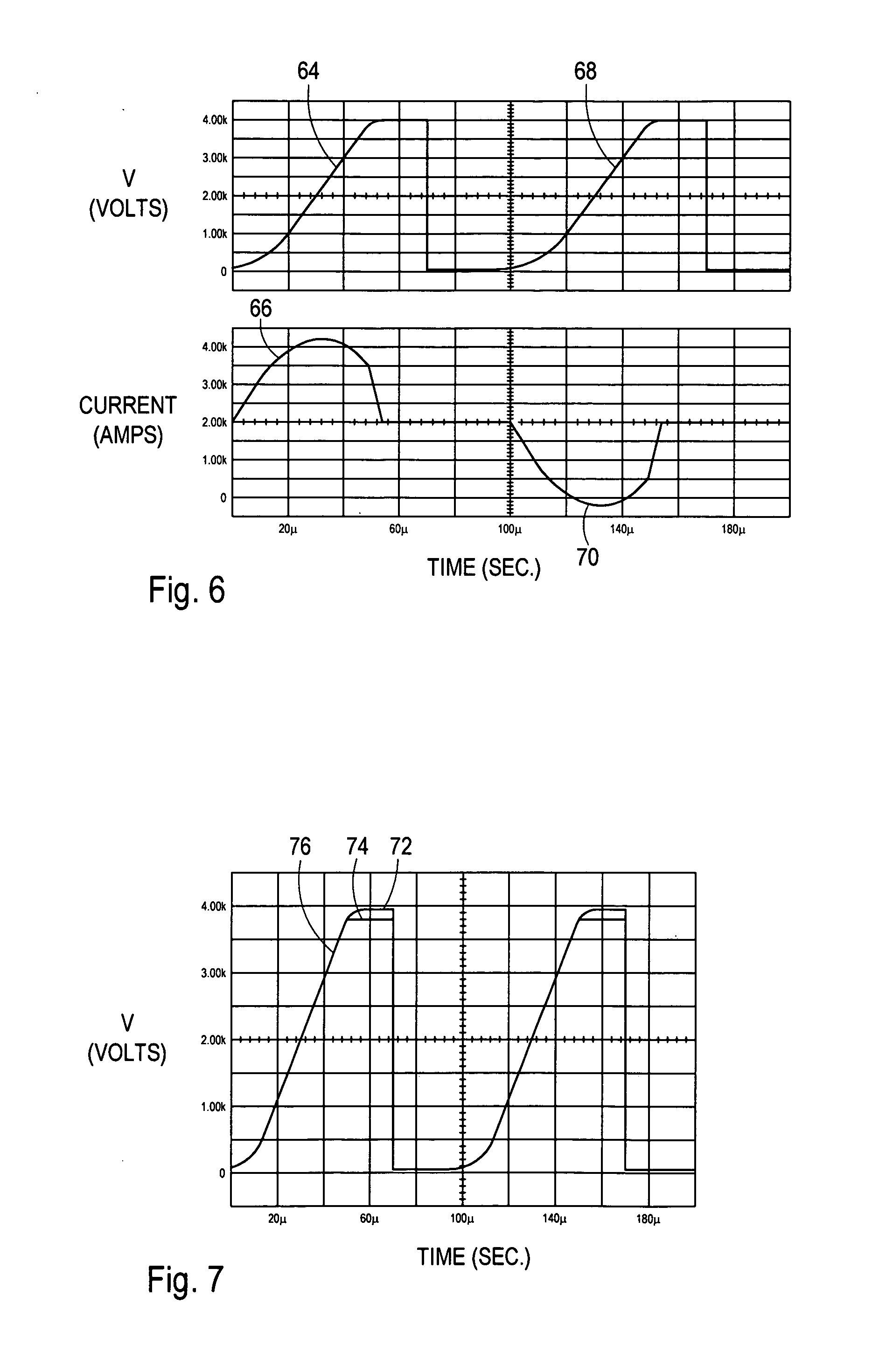
One problem associated with the above-described resonant charge circuit is the regulation of the maximum voltage across the capacitor.

Method used


Image

  • Resonant charge power supply topology for high pulse rate pulsed power systems
  • Resonant charge power supply topology for high pulse rate pulsed power systems
  • Resonant charge power supply topology for high pulse rate pulsed power systems

Examples


Embodiment Construction

[0008] The present invention is directed to a power supply system that charges a capacitor with relatively high energy pulses, at a relatively high pulse repetition rate. The system works in conjunction with a load (e.g. UAV laser lamps) that is switchably connected to the capacitor. At the end of each pulse, the load is connected (i.e. switched) across the capacitor. This then discharges the capacitor and energizes the load.

[0009] For the system, a voltage transformer having a high voltage side, a low voltage side and a transformer core is provided. In addition, a resonant circuit having an inductor and a capacitor is connected to the transformer. Specifically, the inductor is connected to the low voltage side of the transformer and the capacitor is connected to the high voltage side of the transformer. With this cooperation of structure, a power supply and switch assembly are connected to the low voltage side of the transformer and configured to generate a pulse in the resonant c...


PUM


Abstract

A system for charging a capacitor with relatively high energy pulses at a relatively high pulse repetition rate includes a voltage transformer. A resonant circuit is established having an inductor connected to the transformer's low voltage side and a capacitor connected to the transformer's high voltage side. A power supply cooperates with a switch assembly to generate a train of pulses, alternating in polarity, in the circuit. With this arrangement, the transformer core is reset after each pulse. A rectifying circuit operates on the alternating polarity pulses to create a train of constant polarity pulses for charging the capacitor. For the system, the maximum charging voltage is regulated by a control circuit having a probe for measuring the voltage across the charging capacitor. This measured voltage is used by the control circuit to selectively operate the switch assembly and regulate the maximum voltage across the capacitor.

Description

FIELD OF THE INVENTION [0001] The present invention pertains generally to electrical power systems. More particularly, the present invention pertains to high voltage, pulsed power systems. The present invention is particularly, but not exclusively, useful as a power system having a capacitor that is charged with pulses at a relatively high pulse repetition rate. BACKGROUND OF THE INVENTION [0002] Several types of modern equipment require an electrical power supply that is capable of producing high energy pulses at very high pulse repetition rate. Examples of these include, but are not limited to, certain laser systems, and more modernly, extreme ultraviolet (EAV) sources for advanced photolithography techniques. [0003] Heretofore, resonant circuits that are configured to charge a capacitor have been employed when power at a high pulse repetition rate has been required. These resonant circuits typically include an inductor in addition to the capacitor. When a power source (e.g. batte...

Claims


Application Information

Patent Timeline
IPC IPC(8): H02M3/24
CPCH02J7/022Y02B70/1433H02M3/3376H02J7/02H02J2207/20Y02B70/10
Inventor BUSHNELL, ANDREW HUGH
Owner GENERAL ATOMICS ELECTRONICS SYST
Learn More