
Expandable reamer apparatus for enlarging boreholes while drilling and methods of use

a technology of expanding reamer and expanding borehole, which is applied in the directions of sealing/packing, borehole/well accessories, survey, etc., can solve the problem of displaced actuation sleeve, and achieve the effect of reducing the ability of drilling mud

Inactive Publication Date: 2007-01-25
BAKER HUGHES OILFIELD OPERATIONS LLC
View PDF56 Cites 18 Cited by
  • Summary
  • Abstract
  • Description
  • Claims
  • Application Information

AI Technical Summary

Benefits of technology

The present invention relates to an expandable reamer that can be used to drill or enlarge a borehole in a subterranean formation. The reamer includes a movable blade assembly that can be expanded to drill or enlarge the borehole. The expandable reamer can be positioned at an initial smaller diameter and then expanded to a larger diameter to ream or drill the borehole. The reamer can be actuated by a sleeve or other mechanism that causes the movable blades to expand. The reamer can also include a biasing element or other mechanism to return the blades to their original position when the actuation sleeve is removed or the force generated by drilling fluid passes through the reduced cross-sectional area of the actuation sleeve is insufficient to move the blades. The reamer can also have adjustable blades or a flow restriction element to control the expansion of the blades. The expandable reamer can be used in drilling or enlarging a borehole in a subterranean formation.

Problems solved by technology

Thus, the drilling fluid passing through the expandable reamer and reduced cross-sectional aperture or orifice may cause the actuation sleeve to be displaced by the force generated thereby.

Method used


Image

  • Expandable reamer apparatus for enlarging boreholes while drilling and methods of use
  • Expandable reamer apparatus for enlarging boreholes while drilling and methods of use
  • Expandable reamer apparatus for enlarging boreholes while drilling and methods of use

Examples


Embodiment Construction

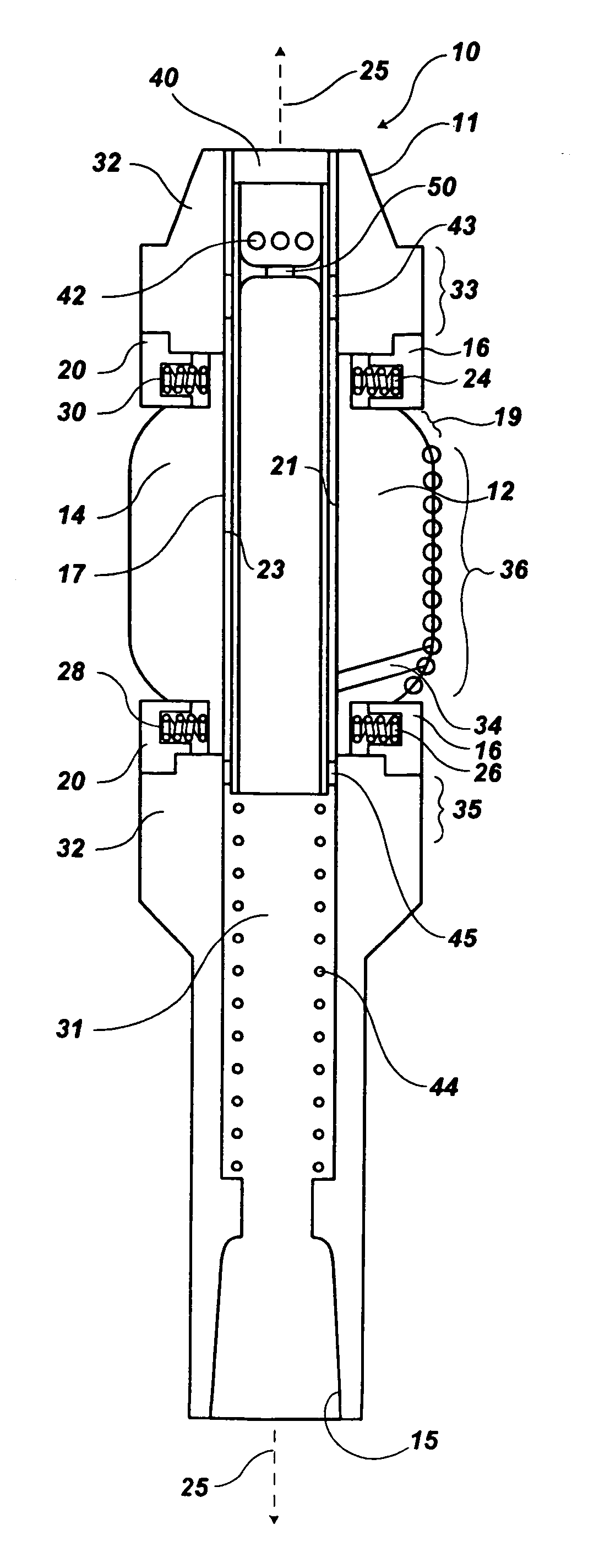
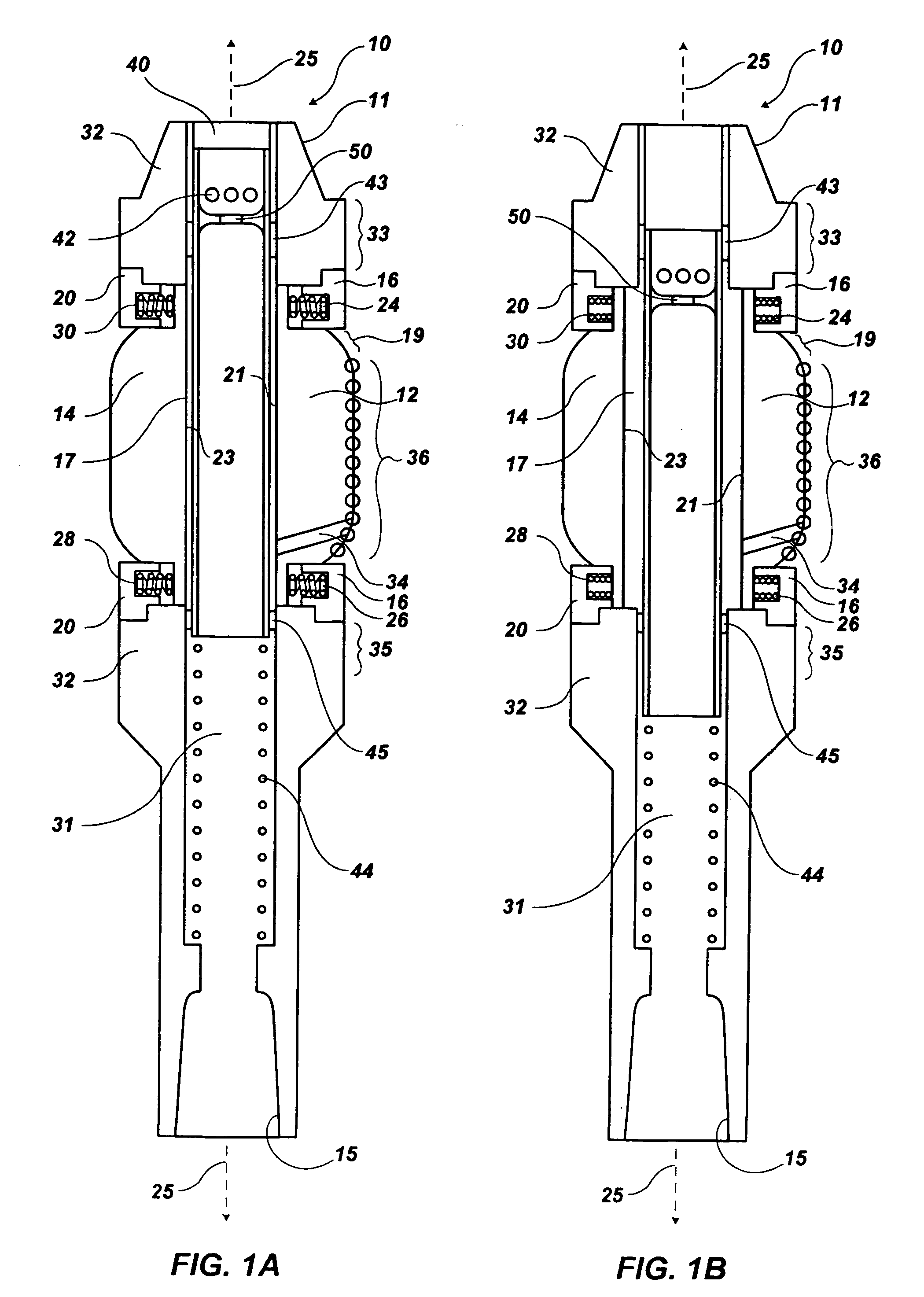
[0071] Referring to FIGS. 1A and 1B of the drawings, each shows a conceptual schematic side view of an expandable reamer 10 of the present invention. Expandable reamer 10 includes a tubular body 32 with a bore 31 extending therethrough, having movable blades 12 and 14 outwardly spaced from the centerline or longitudinal axis 25 of the tubular body 32. Tubular body 32 includes a male-threaded pin connection 11 as well as a female-threaded box connection 15, as known in the art. Movable blades 12 and 14 may each carry a plurality of cutting elements 36. Cutting elements 36 are shown only on movable blade 12, as the cutting elements on movable blade 14 would be facing in the direction of rotation of the expandable reamer 10 and, therefore, may not be visible in the view depicted in FIG. 1A. Cutting elements 36 may comprise PDC cutting elements, thermally stable PDC cutting elements (also known as “TSPs”), superabrasive impregnated cutting elements, tungsten carbide cutting elements, an...


PUM


Abstract

An expandable reamer apparatus and methods for reaming a borehole, wherein a laterally movable blade carried by a tubular body may be selectively positioned at an inward position and an expanded position. The laterally movable blade, held inwardly by blade-biasing elements, may be forced outwardly by drilling fluid selectively allowed to communicate therewith by way of an actuation sleeve disposed within the tubular body. Alternatively, a separation element may transmit force or pressure from the drilling fluid to the movable blade. Further, a chamber in communication with the movable blade may be pressurized by way of a downhole turbine or pump. A ridged seal wiper, compensator, movable bearing pad, fixed bearing pad preceding the movable blade, or adjustable spacer element to alter expanded blade position may be included within the expandable reamer. In addition, a drilling fluid pressure response indicating an operational characteristic of the expandable reamer may be generated.

Description

CROSS-REFERENCE TO RELATED APPLICATIONS [0001] This application is a continuation of application Ser. No. 10 / 624,952, filed Jul. 22, 2003, pending, which claims the benefit of U.S. Provisional Patent Application Ser. No. 60 / 399,531, filed Jul. 30, 2002, for EXPANDABLE REAMER APPARATUS FOR ENLARGING BOREHOLES WHILE DRILLING AND METHOD OF USE.BACKGROUND OF THE INVENTION [0002] 1. Field of the Invention [0003] The present invention relates generally to an expandable reamer apparatus and methods for drilling a subterranean borehole and, more specifically, to enlarging a subterranean borehole beneath a casing or liner. The expandable reamer may comprise a tubular body configured with movable blades that may be displaced radially or laterally outwardly, the movable blades having cutting elements attached thereto. [0004] 2. State of the Art [0005] Drill bits for drilling oil, gas, and geothermal wells, and other similar uses typically comprise a solid metal or composite matrix-type metal b...

Claims


Application Information

Patent Timeline
Patent Type & Authority Applications(United States)
IPC IPC(8): E21B10/26E21B10/32E21B34/14
CPCE21B10/322E21B34/14E21B4/00E21B4/04E21B47/18E21B44/005E21B10/32E21B17/1014E21B7/00E21B7/28E21B17/10E21B2200/06
Inventor RADFORD, STEVEN R.IRELAND, KELLY D.GAUTAM, ANURAGLAING, ROBERT A.MUMMA, MATTHEW D.PRITCHARD, DARYL L.
Owner BAKER HUGHES OILFIELD OPERATIONS LLC
Learn More