
Method and system for motion compensated fine granularity scalable video coding with drift control

Inactive Publication Date: 2007-01-18
NOKIA CORP
View PDF6 Cites 71 Cited by
  • Summary
  • Abstract
  • Description
  • Claims
  • Application Information

AI Technical Summary

Benefits of technology

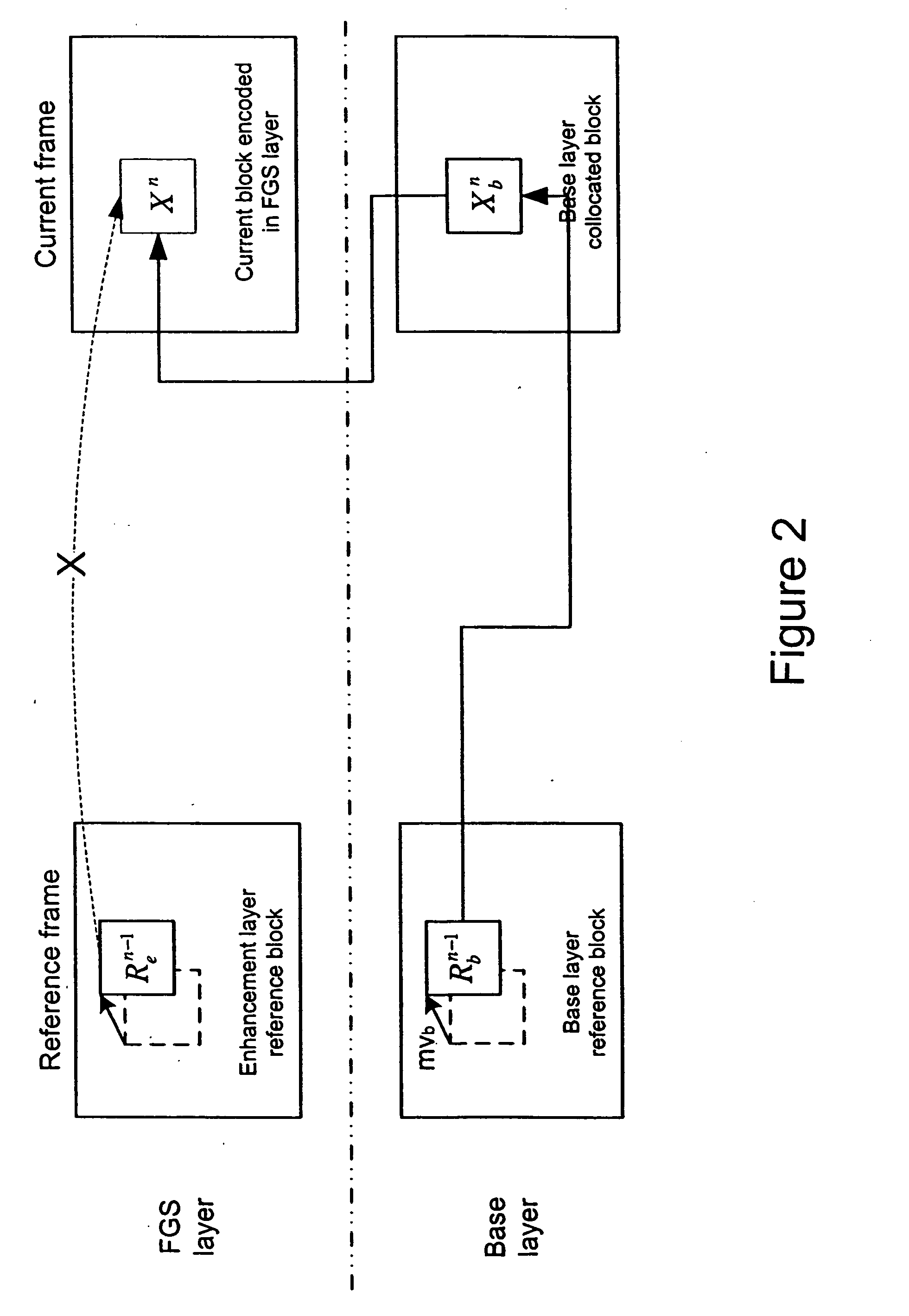
[0015] The present invention provides a fine granularity SNR scalable video codec that exploits the temporal redundancy in the FGS layer in order to improve the coding performance while the drift is controlled. More specifically the present invention focuses on how the reference blocks used in predictive coding in FGS layer should be formed, and the signaling and mechanism that are needed to control the process.
[0016] The present invention improves the efficiency of FGS coding, especially under low-delay constraints. The present invention is effective in controlling the drift, and thus a fine granularity scalability (FGS) coder of better performance can be designed accordingly.

Problems solved by technology

When temporal prediction is carried out according to the second and the third methods, mismatch is likely to exist between the reference frames used by the encoder and those by the decoder.
If the mismatch accumulates at the decoder side, the quality of reconstructed video suffers.
Many video coding systems are designed to be drift-free because the accumulated errors could result in artifacts in the reconstructed video.
This approach has the maximal bitstream flexibility since truncation of the FGS stream of one frame will not affect the decoding of other frames, but the coding performance is not competitive.
However, since the FGS layer of any frame can be partially decoded, the error caused by the difference between the reference frames used in the decoder and encoder will accumulate and the drift is resulted.
However, JSVM1.0 FGS coder is not designed to manage the drift.
In this case, the JSVM1.0 FGS coder is very inefficient because every frame is coded as an anchor frame.
However, the upper enhancement layer has a drift problem because of the partial decoding of the FGS layer.

Method used


Image

  • Method and system for motion compensated fine granularity scalable video coding with drift control
  • Method and system for motion compensated fine granularity scalable video coding with drift control
  • Method and system for motion compensated fine granularity scalable video coding with drift control

Examples


Embodiment Construction

[0034] As in typical predictive coding in a non-scalable single layer video codec, to code a block Xn of size M×N pixels in the FGS layer, a reference block Ran is used. Ran is formed adaptively from a reference block Xbn from the base layer reconstructed frame and a reference block Ren−1 from the enhancement layer reference frame based on the coefficients coded in the base layer, Qbn. FIG. 5 gives the relationship among these blocks. Here a block is a rectangular area in the frame. The size of a block in the spatial domain is the same as the size of the corresponding block in the coefficient domain.

[0035] In the FGS coder, according to the present invention, the same original frame is coded in the enhancement layer and the base layer, but at different quality levels. The base layer collocated block refers to the block coded in the base layer that corresponds to the same original block that is being processed in the enhancement layer.

[0036] In the following, Qbn is a block of quan...


PUM


Abstract

An adaptively formed reference block is used for coding a block in a current frame in the enhancement layer. In particular, the reference block is formed from a reference block in base layer reconstructed frame and a reference block in the enhancement layer reference frame together with a base layer reconstructed prediction residual block. Furthermore, the reference block for coding is adjusted depending on the transform coefficients of the base layer reconstructed residual layer. Moreover, the actual reference signal used for coding is a weighted average of a reference signal from the reconstructed frame in the base layer and a reference signal from the enhancement layer reference frame together with a base layer reconstruction prediction residual.

Description

[0001] The present invention is based on and claims priority to U.S. Provisional Patent Application No. 60 / 670,797, filed Apr. 12, 2005; U.S. Provisional Patent Application No. 60 / 671,263, filed Apr. 13, 2005; and U.S. Provisional Patent Application No. 60 / 724,521, filed Oct. 6, 2005.FIELD OF THE INVENTION [0002] This invention relates to the field of video coding, and more specifically to scalable video coding. BACKGROUND OF THE INVENTION [0003] In video coding, temporal redundancy existing among video frames can be minimized by predicting a video frame based on other video frames. These other frames are called the reference frames. Temporal prediction can be carried out in different ways: [0004] The decoder uses the same reference frames as those used by the encoder. This is the most common method in conventional non-scalable video coding. In normal operations, there should not be any mismatch between the reference frames used by the encoder and those by the decoder. [0005] The en...

Claims


Application Information

Patent Timeline
IPC IPC(8): H04B1/66H04N11/04
CPCH04N19/61H04N19/34H04N19/29H04N19/48
Inventor BAO, YILIANGKARCZEWICZ, MARTARIDGE, JUSTINWANG, XIANGLIN
Owner NOKIA CORP
Learn More