
Virtual electronic perimeter fence with solar powered lights

a solar-powered, electronic technology, applied in the field of virtual electronic perimeter fences, can solve the problems of compromising the security of the perimeter fence, prior electronic fences,

Inactive Publication Date: 2007-01-18
SMARTPOOL
View PDF4 Cites 17 Cited by
  • Summary
  • Abstract
  • Description
  • Claims
  • Application Information

AI Technical Summary

Benefits of technology

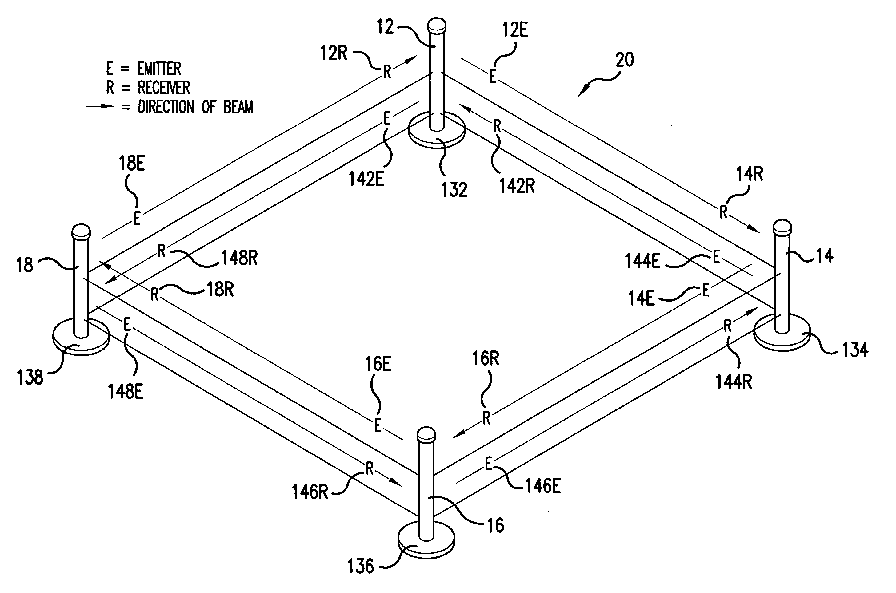
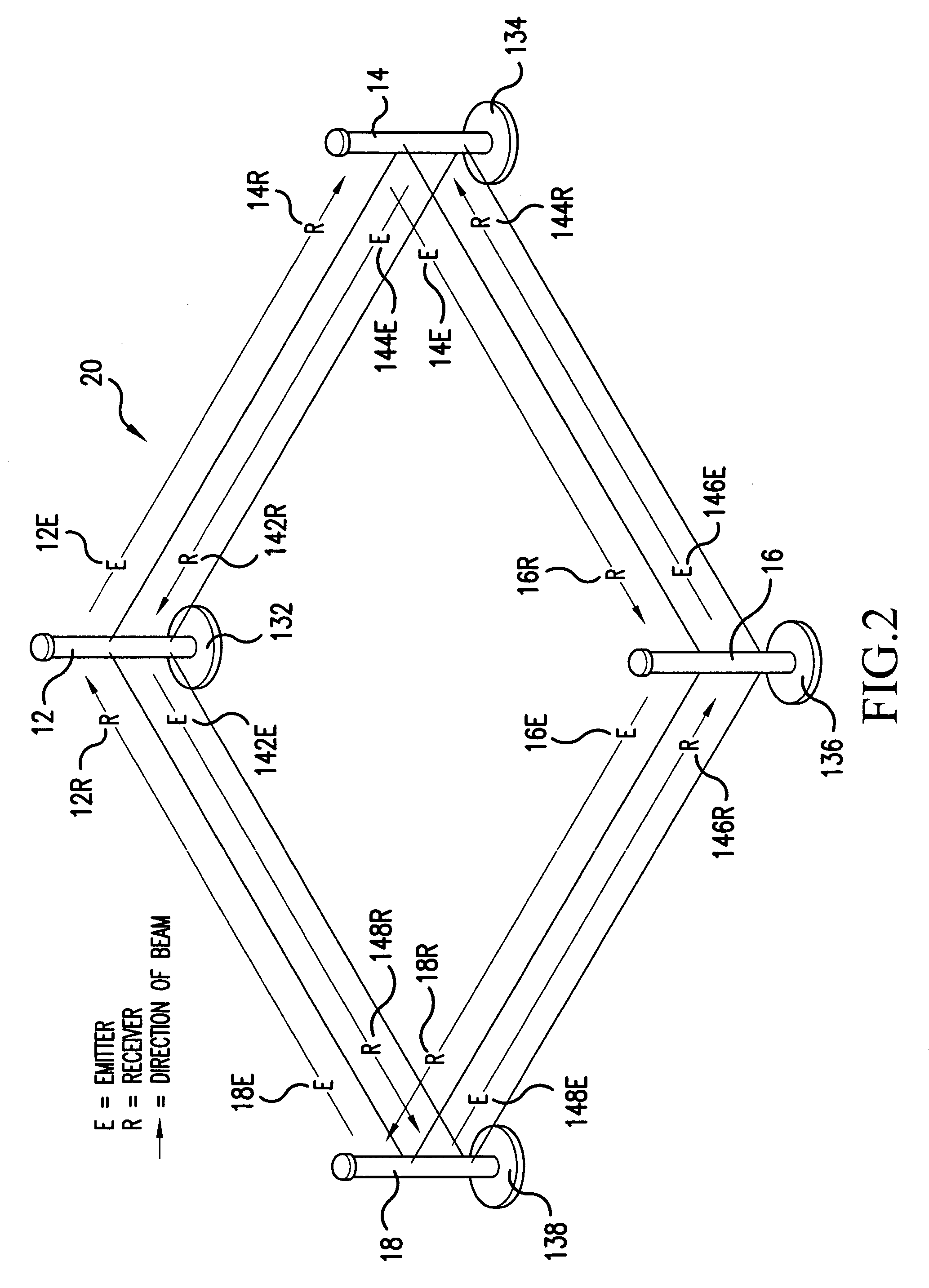
[0007] It is an object of the present invention to provide a combination of elements wherein a fence post can be equipped with a solar panel and a light for providing illumination to the area adjacent to the fence post. In addition, a first fence post is provided that includes an emitter for emitting a beam of infrared light at a first frequency to a second fence post. The second fence post includes a receiver that is designed to receive the first frequency of infrared light emitted from the first fence post. The second fence post includes an emitter for emitting a beam of infrared light at a second frequency to a third fence post. The third fence post includes a receiver that is designed to receive the second frequency of infrared light emitted from the second fence post. The third fence post includes an emitter for emitting a beam of infrared light at a third frequency to a fourth fence post. The fourth fence post includes a receiver that is designed to receive the third frequency of infrared light emitted from the third fence post. The fourth fence post includes an emitter for emitting a beam of infrared light at a fourth frequency to the first fence post. The first fence post includes a receiver that is designed to receive the fourth frequency of infrared light emitted from the fourth fence post. In this way, a particular frequency of infrared light is emitted and received by adjacent fence posts without the possibility of a cross-signal connection.
[0008] The present invention provides a combination of elements wherein the frequency of infrared light is orchestrated between adjacent fence posts to provide a virtual electronic perimeter fence. The orchestration of the infrared light between adjacent fence posts provides security for generating an alarm if data is not properly emitted and received while eliminating cross-signals between fence posts.
[0011] Each fence post may include a solar panel that may be connected to a battery or other energy storage device for facilitating an overflow of electrical energy and for supplying the post with power during the evening or other times of darkness. This embodiment eliminates the need to run wires for providing power to the system.

Problems solved by technology

A problem results in prior electronic fences due to the fact that the post do not include any illumination.
However, since the first fence post is actually transmitting a beam of light to the third fence post, the secured area is actually compromised with a portion of the secured area being open to intruders.

Method used


Image

  • Virtual electronic perimeter fence with solar powered lights
  • Virtual electronic perimeter fence with solar powered lights
  • Virtual electronic perimeter fence with solar powered lights

Examples


Embodiment Construction

[0033] As illustrated in FIG. 1-4, a virtual electronic perimeter fence 20 is provided with a first fence post 12 including an emitter 12E for emitting a beam of infrared light at a first frequency. A second fence post 14 is displaced a predetermined distance relative to the first fence post 12. The second fence post 14 includes a receiver 14R for receiving the first frequency of infrared light emitted from the emitter 12E disposed on the first fence post 12. The second fence post 14 includes an emitter 14E for emitting a beam of infrared light at a second frequency. A third fence post 16 includes a receiver 16R for receiving the second frequency of infrared light emitted from the emitter 14E disposed on the second fence post 14. The third fence post 16 includes an emitter 16E for emitting a beam of infrared light at a third frequency.

[0034] In one embodiment of the present invention, the third emitter 16E may be positioned to transmit the beam of infrared light at the third freque...


PUM


Abstract

A virtual electronic perimeter fence includes at least a first, second and third fence post each including an emitter for emitting a beam of infrared light at a predetermined frequency. The first, second and third fence posts include a receiver for receiving the predetermined frequency of infrared light emitted from a designated fence post. A beam of infrared light of a first frequency is emitted from the first fence post to the second fence post and a beam of infrared light of a second frequency is emitted from the second fence post to the third fence post and infrared light of a third frequency is emitted from the third fence post to the first fence post for providing a virtual electronic perimeter fence that provides an alarm if an interruption occurs in the beam of infrared light while eliminating cross-signals therebetween. A light, sound and video system may be provided.

Description

CROSS-REFERENCE TO RELATED APPLICATIONS [0001] The present application claims priority under 35 USC 119 to U.S. Provisional Patent Application Nos. 60 / 675,877 filed on Apr. 29, 2005 and 60 / 722,416 filed on Oct. 3, 2005 the entire contents of which are hereby incorporated by reference.BACKGROUND OF THE INVENTION [0002] 1. Field of the Invention [0003] The present invention is directed to a virtual electronic perimeter fence that includes solar panels and lights for illumination and speakers for sound. More specifically, to solar panels and lights that are used together with an electronic perimeter fence that utilizes infrared light of a predetermined frequency that is orchestrated between adjacent fence posts to provide security for generating an alarm if data is not properly emitted and received while eliminating cross-signals between fence posts. [0004] 2. Description of Background Art [0005] Heretofore, fences have been available with fence post positioned at predetermined interva...

Claims


Application Information

Patent Timeline
IPC IPC(8): A01K3/00
CPCA01K3/00G08B21/086G08B13/183
Inventor MIKUSKI, SHAWNTEDER, REINHOLSTEIN, RICHARD
Owner SMARTPOOL
Learn More