Grease protecting apparatus for heat sink

a technology of grease protection and heat sink, which is applied in the direction of applications, instruments, caps, etc., can solve the problems of contaminated surrounding objects, wing deformation, and wing deformation, so as to reduce internal stress, reduce the tendency of wing deformation after bonded to the bottom surface of the heat sink, and increase the flexibility of the connecting portions

Inactive Publication Date: 2007-01-18
HON HAI PRECISION IND CO LTD
View PDF8 Cites 11 Cited by
  • Summary
  • Abstract
  • Description
  • Claims
  • Application Information

AI Technical Summary

Benefits of technology

[0005] The present invention relates to a grease protecting apparatus. According to a preferred embodiment of the present invention, the grease protecting apparatus includes a heat sink, and a grease cover. The heat sink includes a bottom surface for contacting with a heat-generating component. A layer of thermal grease is spread on the bottom surface of the heat sink. The grease cover is attached to the bottom surface of the heat sink and covers the grease to protect the grease from contamination. The cover includes a main body defining a protecting space therein for covering the grease, and two wings extending from two opposite sides of the main body. Two sheets of adhesive are applied on the wings, respectively. The adhesive is used to attach the wings and accordingly the grease cover to the bottom surface of the heat sink. The wings define a plurality of perforations in connecting portions between the main body and the wings, for increasing flexibility of the connecting portions of the grease cover, thereby reducing internal stress caused by forming the cover in affecting the wings. Thus, a tendency of deformation of the wings after they are bonded to the bottom surface of the heat sink is lessened. Accordingly, the grease cover is firmly attached to the bottom surface of the heat sink.

Problems solved by technology

Since the thermal grease is not solid at ambient temperature, it may contaminate surrounding articles or be contaminated by dust or foreign particles before the heat sink is assembled to the electronic component.
This deformation may cause the wings not to be horizontally oriented, thereby making the wings have a tendency to separate from the bottom surface of the heat sink after the wings are adhered to the heat sink.

Method used


Image

  • Grease protecting apparatus for heat sink
  • Grease protecting apparatus for heat sink
  • Grease protecting apparatus for heat sink

Examples


Embodiment Construction

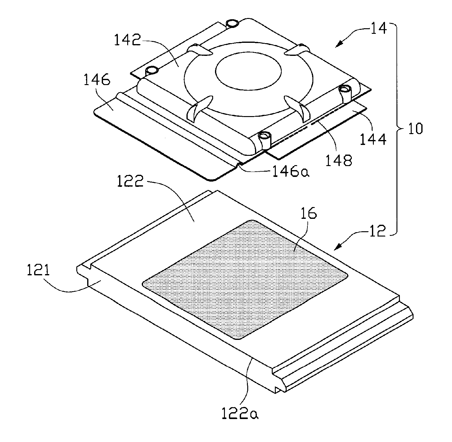
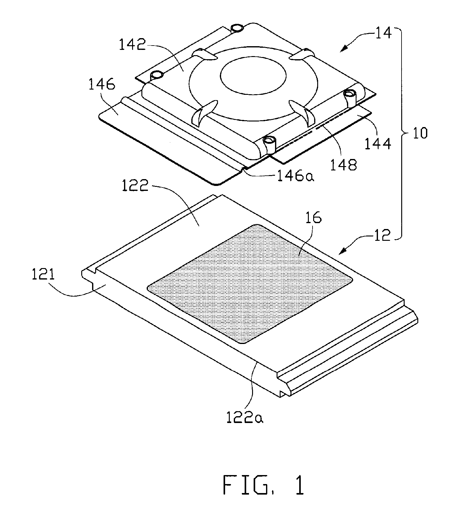
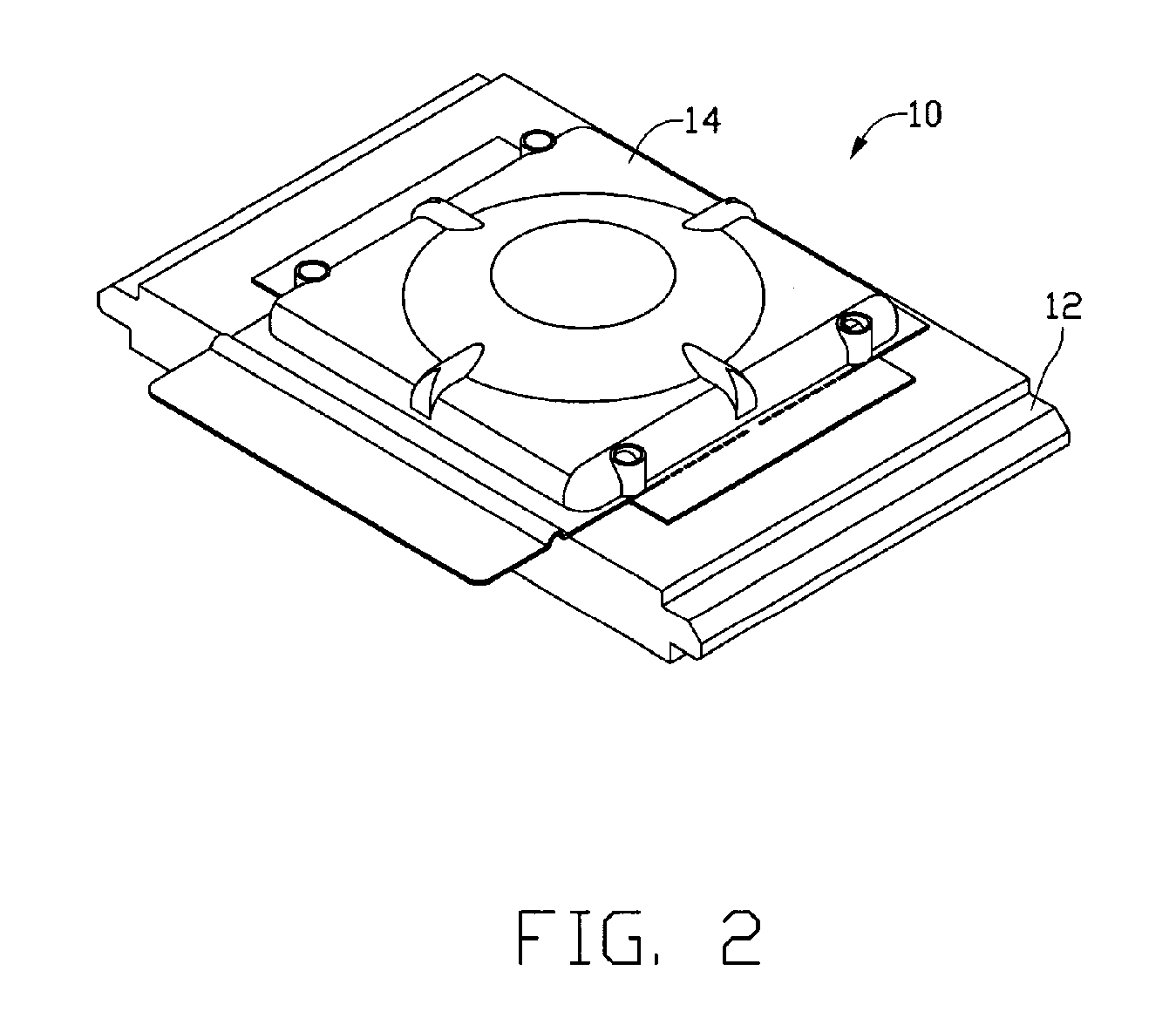
[0012] Referring to FIGS. 1 and 2, a grease protecting apparatus 10 according to a preferred embodiment of the present invention includes a heat sink 12, and a grease cover 14. A layer of thermal grease 16 is spread on a middle portion of a bottom surface 122 of a base 121 of the heat sink 12, for improving heat conductivity between the heat sink 12 and an electronic heat-generating component (not shown) to which the heat sink 12 is to be mounted for absorbing heat therefrom. The cover 14 is attached to the bottom surface 122 of the base 121 of the heat sink 12, for enclosing the thermal grease 16, thereby preventing the thermal grease 16 from contaminating surrounding articles or being contaminated by dust or foreign articles.

[0013] Particularly referring to FIGS. 3 and 4, the grease cover 14 is made of plastics materials, and includes a rectangular main body 142 with four sidewalls 142a, 142b, 142c, and 142d disposed around four sides of a top cover 142e of the main body 142, res...


PUM


Abstract

A grease protecting apparatus (10) includes a heat sink (12), and a grease cover (14). The heat sink includes a bottom surface (122) for contacting with a heat-generating component. A layer of thermal grease (16) is spread on the bottom surface of the heat sink. The grease cover is attached to the bottom surface of the heat sink and covers the grease to protect the grease from contamination. The cover includes a main body (142) defining a protecting space (143) therein for covering the grease, and two wings (144) extending from two opposite sides of the main body for attaching the grease cover to the bottom surface of the heat sink. The wings defines a plurality of perforations (148) therein to make the wings be capable of tilted upwardly and downwardly.

Description

FIELD OF THE INVENTION [0001] The present invention relates generally to a grease protecting apparatus, and particularly to a grease protecting cover to separate thermal grease spread on a heat dissipating apparatus from surrounding articles. DESCRIPTION OF RELATED ART [0002] A layer of thermal grease is usually spread on a bottom surface of a heat sink to improve heat conductivity between the heat sink and an electronic heat-generating component. The heat generated by the electronic component causes the thermal grease to become liquid, enabling the thermal grease to fill in air gaps formed between the heat sink and the electronic component, thereby improving heat conductivity between the heat sink and the electronic component. [0003] Since the thermal grease is not solid at ambient temperature, it may contaminate surrounding articles or be contaminated by dust or foreign particles before the heat sink is assembled to the electronic component. To avoid the contamination, a grease pr...

Claims


Application Information

Patent Timeline
Patent Type & Authority Applications(United States)
IPC IPC(8): H05K7/20B65D41/00G06F1/20
CPCH05K7/20472
Inventor LIN, YEU-LIHCHEN, CHIN-LUNGSHENG, JIAN-QING
Owner HON HAI PRECISION IND CO LTD
Why Eureka
Try Eureka