
Illumination system for optical inspection

a technology of optical inspection and illumination system, which is applied in the field of optical inspection, can solve problems such as reducing process yield, and achieve the effect of high data collection rate and high resolution

Active Publication Date: 2007-01-11
APPLIED MATERIALS INC +1
View PDF47 Cites 22 Cited by
  • Summary
  • Abstract
  • Description
  • Claims
  • Application Information

AI Technical Summary

Benefits of technology

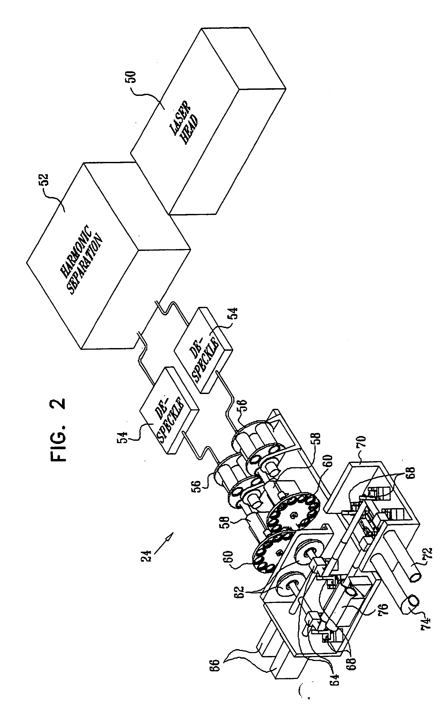
The present invention provides improved methods and apparatus for illumination of a surface of a sample, such as a semiconductor wafer, with high resolution and high data collection rates. The invention reduces speckle contrast on the surface of the sample by processing the pulsed laser beam to reduce its coherence before it reaches the surface. This is done by using a bundle of optical fibers of different lengths or a high-speed scanner. The invention also allows for simultaneous inspection of multiple areas on the sample by using different wavelengths of laser radiation. The laser source is a pulsed laser beam that emits radiation with low speckle contrast. The invention also includes an illumination module with an optical switch that directs both beams of laser radiation simultaneously and independently, allowing for either normal or oblique irradiation of the sample.

Problems solved by technology

Defects can cause device failures, thus substantially reducing the process yield.

Method used


Image

  • Illumination system for optical inspection
  • Illumination system for optical inspection
  • Illumination system for optical inspection

Examples


Embodiment Construction

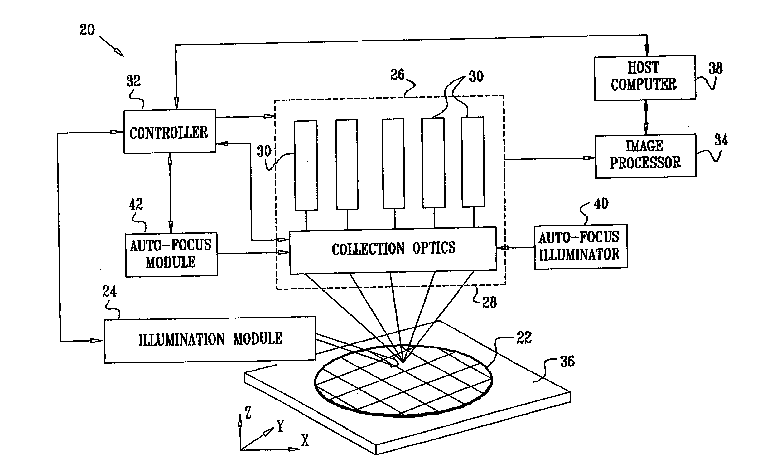
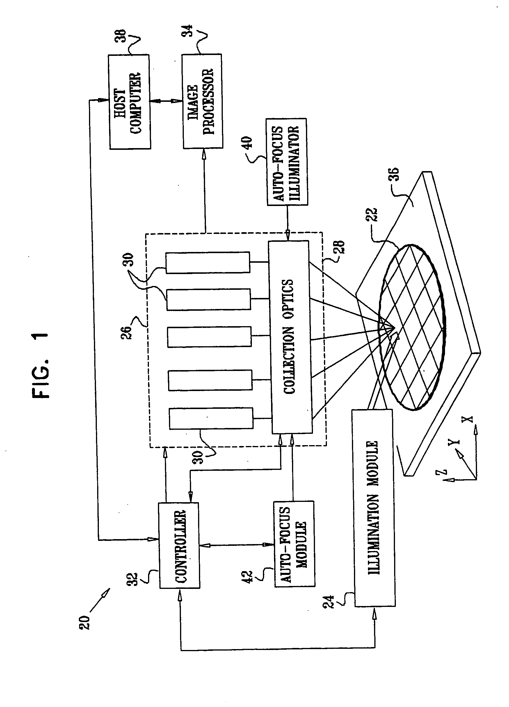
[0053]FIG. 1 is a block diagram that schematically illustrates a system 20 for optical inspection of a semiconductor wafer 22, in accordance with an embodiment of the present invention. Typically, wafer 22 is patterned, using methods of semiconductor device production known in the art, and system 20 applies dark-field optical techniques to detect defects on the surface of the wafer. Alternatively, however, the principles embodied in system 20 may be applied to unpatterned wafers and to inspection of other types of samples and surfaces, as well, such as masks and reticles. Furthermore, although system 20 is dedicated to dark-field inspection, aspects of the present invention may also be applied in bright-field inspection, as well as in other areas of illumination, inspection and imaging.

[0054] System 20 comprises an illumination module 24, which illuminates the surface of sample 22 using pulsed laser radiation. Typically, module 24 is able to emit the laser radiation selectably at t...


PUM

PropertyMeasurementUnit
sizeaaaaaaaaaa
sizeaaaaaaaaaa
angleaaaaaaaaaa

Abstract

Apparatus for generating optical radiation includes a laser, which is configured to operate in multiple transverse modes simultaneously so as to generate an input beam, which is characterized by a first speckle contrast. The transverse modes of the input beam are optically mixed so as to generate an output beam have a second speckle contrast, which is substantially less than the first speckle contrast.

Description

CROSS-REFERENCE TO RELATED APPLICATIONS [0001] This application is related to two other U.S. patent applications, filed on even date, entitled “Dark Field Inspection System” and “Inspection System with Oblique Viewing Angle.” Both of these related applications are incorporated herein by reference.FIELD OF THE INVENTION [0002] The present invention relates generally to optical inspection, and specifically to methods and apparatus for inspection of solid-state surfaces, such as semiconductor wafers, and detection of features and defects thereon. BACKGROUND OF THE INVENTION [0003] Optical inspection is commonly used in semiconductor device manufacturing to detect defects on the surface of a wafer, such as contaminant particles, scratches and unremoved portions of material layers. Defects can cause device failures, thus substantially reducing the process yield. Therefore, careful inspection is required to verify the cleanliness and quality both of unpatterned wafers and of patterned waf...

Claims


Application Information

Patent Timeline
Patent Type & Authority Applications(United States)
IPC IPC(8): G01N21/88G01N21/47G01N21/95G01N21/956G02B27/48
CPCG01N21/47G01N2201/0697G01N21/8806G01N21/94G01N21/9501G01N21/95607G01N21/95623G01N2021/1772G01N2021/4711G01N2021/4735G01N2021/479G01N2021/4792G01N2021/8822G01N2021/8845G01N21/4788H01S3/005
Inventor NAFTALI, RONGUETTA, AVISHAYFELDMAN, HAIMSHOHAM, DORON
Owner APPLIED MATERIALS INC
Learn More