Cryostat configuration with thermally compensated centering

a cryostat and centering technology, applied in the field of cryostat configuration, can solve the problems of containers contacting each other, increasing cryogenic losses, heat bridges, etc., and achieve the effect of preventing excessive bending

Active Publication Date: 2007-01-11
BRUKER SWITZERLAND AG
View PDF8 Cites 8 Cited by
  • Summary
  • Abstract
  • Description
  • Claims
  • Application Information

AI Technical Summary

Benefits of technology

[0023] In one preferred further development of this embodiment, the first component of the actuator is displaceably connected to the second component of the actuator which is designed as a tube or channel, at the closed tube end of the second component via an axial screw connection in such a manner that the first component can be displaced relative to the second component in the direction of the tube axis. Since the two elements are connected, a change in length or displacement of one element has an effect on the other. Moreover, the screw connection already permits pretensioning of the elements in the warm state, relative to the outer container preferably the outer jacket.
[0024] A guiding sleeve is advantageously mounted around the first component of the actuator, which is solidly supported on the first element and whose outer diameter is large enough to leave play between the guiding sleeve and the second component. This prevents excessive bending of the first component or an excessive bending load at the connecting point of the two components when the first component is displaced relative to the second componen

Problems solved by technology

This would disadvantageously lead to heat bridges and an increase in cryogenic losses.
These problems are aggravated when, in addition to the suspension tubes, asymmetrically disposed vertical openings (neck tubes) are required between the helium container or nitrogen container and the outer vacuum shell, as e.g. in vertical cryostats,

Method used


Image

  • Cryostat configuration with thermally compensated centering
  • Cryostat configuration with thermally compensated centering
  • Cryostat configuration with thermally compensated centering

Examples


Embodiment Construction

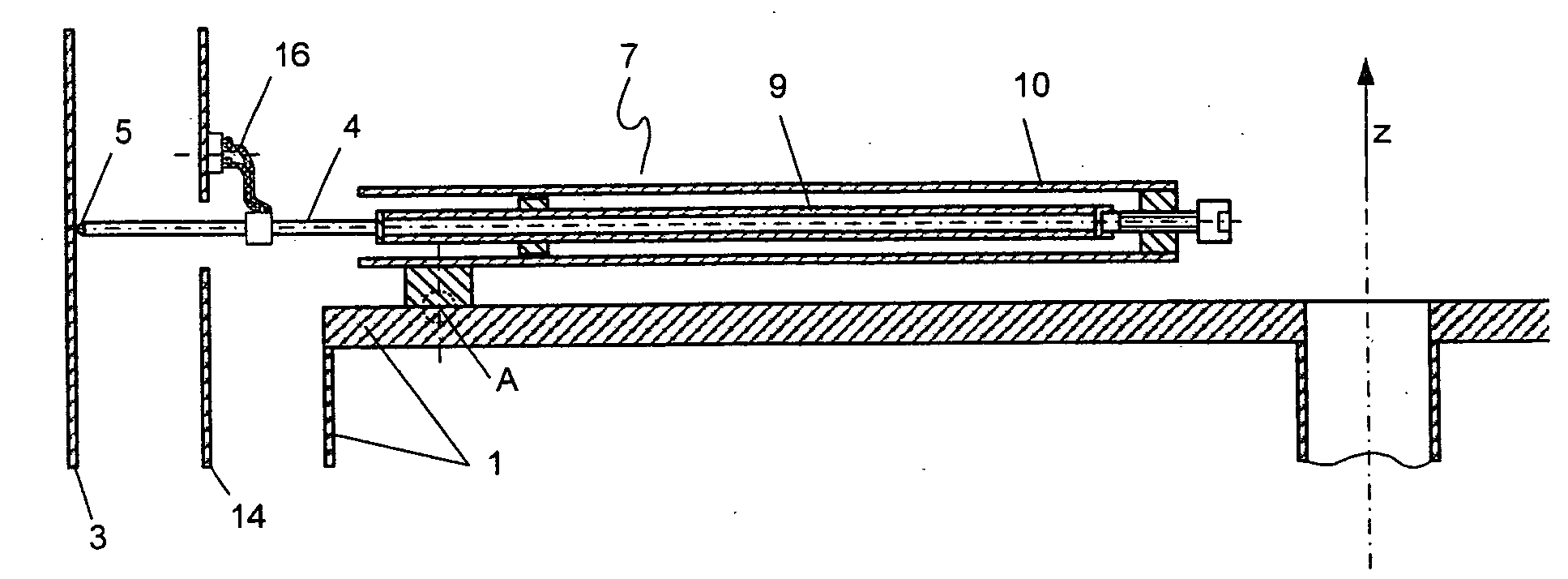
[0049]FIGS. 1a and 1b show embodiments of the inventive cryostat configuration with a cryocontainer 1 for keeping a cryogenic liquid, which is mounted to an outer jacket 3 of the cryostat configuration via suspension tubes 2. Centering devices which are connected to the cryocontainer 1 and contact the outer jacket 3 via centering elements 4 are provided at the lower end of the cryocontainer 1 in order to center the cryocontainer 1 relative to the outer jacket 3 of the cryostat configuration. The ends 5 of the centering elements 4 abut the outer jacket 3 or are mounted thereto. At the other end 6, the centering elements are connected to an actuator 7 which exerts pressure or tension onto the centering element 4.

[0050]FIGS. 2a and 2b show embodiments of the inventive cryostat configuration, wherein the cryocontainer 1 comprises a neck tube designed as asymmetric opening 8. This asymmetric configuration of the opening 8 is shown, in particular, in FIG. 2b.

[0051] Three centering eleme...


PUM


Abstract

Cryostat configuration for keeping cryogenic fluids in at least one cryocontainer (1) which is suspended on thermally insulating suspension tubes (2) and/or suspension devices which are connected to an outer jacket (3) of the cryostat configuration, wherein the at least one cryocontainer (1) is centered relative to a container disposed further outside, preferably the outer jacket (3), using at least three centering elements (4) which are distributed about the periphery of the cryocontainer (1), wherein one end (5) of each centering element (4) abuts or is connected to the container disposed further outside, characterized in that in at least one of the cryocontainers (1), each end (6) of the centering elements (4) facing away from the outer jacket (3) is connected to an actuator (7) which exerts a pressure or tensile force on the respective centering element (4), and which is mounted to the cryocontainer (1) at at least one contact point (A, A′, B, B′), wherein, through fixation of the actuator (7) to the cryocontainer (1) at the contact point (A, A′, B, B′), through thermal changes in size of the cryocontainer (1), through thermal changes in sizes of individual components of the actuator (7), and optionally through mechanical translation, a mechanical tension is generated in the corresponding centering elements (4) such that the centering elements (4) remain loaded with a nearly constant pressure or tension, preferably in the range of ±10% of the pressure or tension prevailing at room temperature and irrespective of the temperatures within the cryostat configuration. This yields a cryostat configuration which permits pressure centering without overloading the centering elements.

Description

[0001] This application claims Paris Convention priority of DE 10 2005 013 620.6 filed Mar. 24, 2005 the complete disclosure of which is hereby incorporated by reference. BACKGROUND OF THE INVENTION [0002] The invention relates to a cryostat configuration for keeping cryogenic fluids in at least one cryocontainer which is suspended from thermally insulating suspension tubes and / or suspension devices which are connected to an outer jacket of the cryostat configuration, wherein the at least one cryocontainer is subjected to thermal effects and is centered relative to a surrounding container, preferably the outer jacket, using at least three centering elements which are distributed about the periphery of the cryocontainer, wherein one end of each centering element abuts or is mounted to a surrounding container. [0003] A cryostat configuration of this type for a superconducting magnet system of a nuclear magnetic resonance (NMR) measuring means is disclosed e.g. in GB 2 015 716 A and in...

Claims


Application Information

Patent Timeline
IPC IPC(8): G01V3/00F25B19/00
CPCF17C13/08G01R33/3815F17C2203/014
Inventor MRAZ, BEATBOESEL, JOHANNES
Owner BRUKER SWITZERLAND AG
Why Eureka
Try Eureka