
Controlling system for cooling fan

a control system and fan technology, applied in the direction of rotors, marine propulsion, vessel construction, etc., can solve the problems of drastic change in fan noise, drastic change in motor speed within a period, and sudden change in fan speed, so as to reduce the drastic fluctuation of consumption power and stabilize the operating power

Inactive Publication Date: 2007-01-11
KOBELCO CONSTR MASCH CO LTD
View PDF18 Cites 10 Cited by
  • Summary
  • Abstract
  • Description
  • Claims
  • Application Information

AI Technical Summary

Benefits of technology

[0008] Accordingly, it is an object of the present invention to provide a controlling system for a cooling fan in which the fan speed is properly controlled in accordance with the temperature of fluid to be cooled while inhibiting the fan speed from fluctuating drastically.
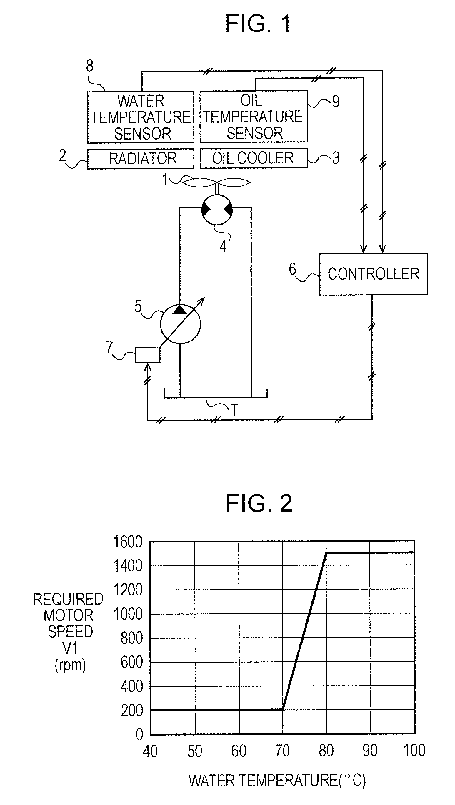
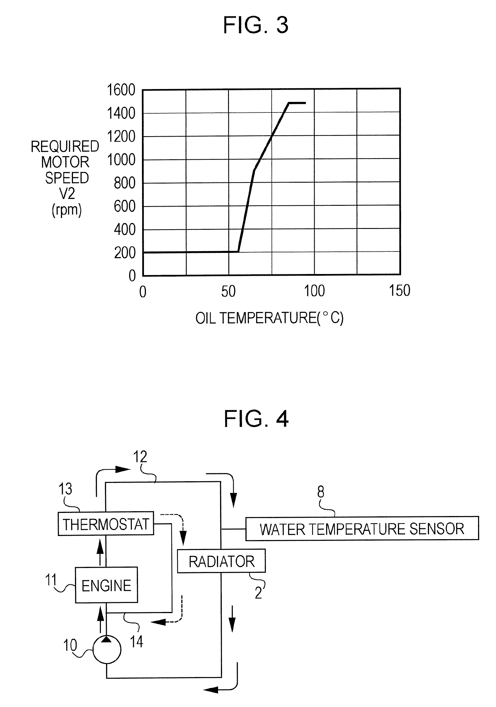
[0011] According to the present invention, the temperature-versus-motor-speed characteristics are preliminarily determined respectively for the multiple kinds of fluids to be cooled. A higher one of the motor speed values (fan speed values), which are determined on the basis of the detected temperature values of the fluids, is selected as a target value. The fluid-pressure motor is thus controlled so that the motor speed thereof reaches the target value. Accordingly, in contrast to the related art in which the speed control is performed by selecting between two speed modes of high speed and low speed, a speed control operation according to the present invention allows for smaller speed changes in association with changes in fluid temperature, that is, a required cooling capability.
[0012] Accordingly, this reduces a drastic change in fan noise and stabilizes the operating power by reducing a drastic fluctuation of consumption power for driving the cooling fan.

Problems solved by technology

However, since a control operation in this technique is performed only for increasing or decreasing the fan speed, there is a drastic change in the fan speed in response to the control operation Especially in hydraulic excavators, even if an excavator is operated to perform the same kind of operation for a certain period of time, the motor speed may change drastically within that period depending on the content (load) of the work.
This may cause a drastic change in fan noise in response to each changing of the motor speed, giving an operator a feeling of insecurity and unpleasantness.
Moreover, the drastic change in the motor speed between the high and low speed modes leads to a large fluctuation of engine power spent for the cooling fan.
Since this significantly changes the power (engine power, fan power) that can be used for the operation of the excavator, the operating speed of attachment components is changed, thus impairing the workability of the excavator.

Method used


Image

  • Controlling system for cooling fan
  • Controlling system for cooling fan
  • Controlling system for cooling fan

Examples


first embodiment

[0022] the present invention will be described below with reference to FIGS. 1 to 4.

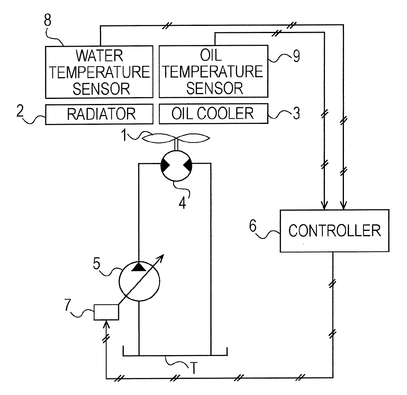
[0023]FIG. 1 illustrates an example in which a radiator 2 serving as the engine cooling device and an oil cooler 3 serving as the working-oil cooling device are cooled with a single cooling fan 1. Therefore, in this example, fluids to be cooled include working oil and coolant water for the radiator 2.

[0024] In FIG. 1, a hydraulic motor 4 is provided for driving the cooling fan 1, and a variable-displacement hydraulic pump 5 is provided as a hydraulic source for the hydraulic motor 4. Moreover, a controller 6 and a pump regulator 7 define speed controlling means for controlling the rotational speed of the hydraulic motor 4. In some cases, the rotational speed will be referred to as a fan speed hereinafter.

[0025] Specifically, the pump regulator 7 is actuated in response to a command signal from the controller 6, by which the capacity of the hydraulic pump 5 is adjusted. Thus, the pump pressure is co...

second embodiment

[0041] A second embodiment according to the present invention will now be described with reference to FIGS. 5 and 6.

[0042] The description of the second embodiment below will only include the differences from the first embodiment.

[0043] Even when the cooling fan 1 rotates at a constant rotational speed, the cooling effect may vary depending on the outside air temperature. In other words, the higher the outside air temperature, the lower the cooling effect, whereas the lower the outside air temperature, the higher the cooling effect. Furthermore, the outside air temperature may also vary by several tens of degrees Celsius depending on location and season.

[0044] Generally, the fan function is set such that a proper cooling capability is attained even when the outside air temperature is at the highest.

[0045] Consequently, controlling the motor speed simply on the basis of the water temperature and the oil temperature may possibly cause overcooling as a result of an excess cooling ca...


PUM


Abstract

A controlling system for a cooling fan according to the present invention includes a fluid-pressure motor for driving the cooling fan; a fluid-pressure pump functioning as a driving source for the fluid-pressure motor; and a controller. The controller determines a target motor speed value by selecting a higher one of required motor speed values respectively corresponding to multiple kinds of fluids to be cooled and controls the fluid-pressure motor so that the motor speed thereof reaches the target motor speed value, each of the required motor speed values being determined from a temperature value of the corresponding fluid detected by a corresponding one of temperature sensors on the basis of a characteristic preliminarily determined by a temperature-versus-motor-speed relationship for the corresponding fluids the characteristic being set for each kind of fluid.

Description

BACKGROUND OF THE INVENTION [0001] 1. Field of the Invention [0002] The present invention relates to controlling systems for cooling fans that are driven by hydraulic motors. [0003] 2. Description of the Related Art [0004] For example, Japanese Patent No. 3238775 discusses a technique for preventing a waste of energy in a driving system of a hydraulic motor that rotates a cooling fan of an engine cooling device and a working-oil cooling device disposed in a hydraulic excavator. Specifically, this is achieved by switching the rotational speed of the hydraulic motor between high and low speed modes in accordance with the temperature of fluid to be cooled. [0005] According to this technique, the motor is rotated at high speed when the temperature values of coolant water and working oil for the motor are higher than a predetermined temperature value, whereas the motor is rotated at low speed when these temperature values are lower than the predetermined temperature value. [0006] However...

Claims


Application Information

Patent Timeline
IPC IPC(8): F01P7/02F01P7/14
CPCF01P7/044F01P2025/34F01P2060/04F01P2025/52F01P2025/40
Inventor SAOTOME, YOSHIMI
Owner KOBELCO CONSTR MASCH CO LTD
Learn More