
Integrated carry-on baggage cart and passenger screening station

Active Publication Date: 2007-01-04
RAPISCAN SYST INC (US)
View PDF18 Cites 46 Cited by
  • Summary
  • Abstract
  • Description
  • Claims
  • Application Information

AI Technical Summary

Benefits of technology

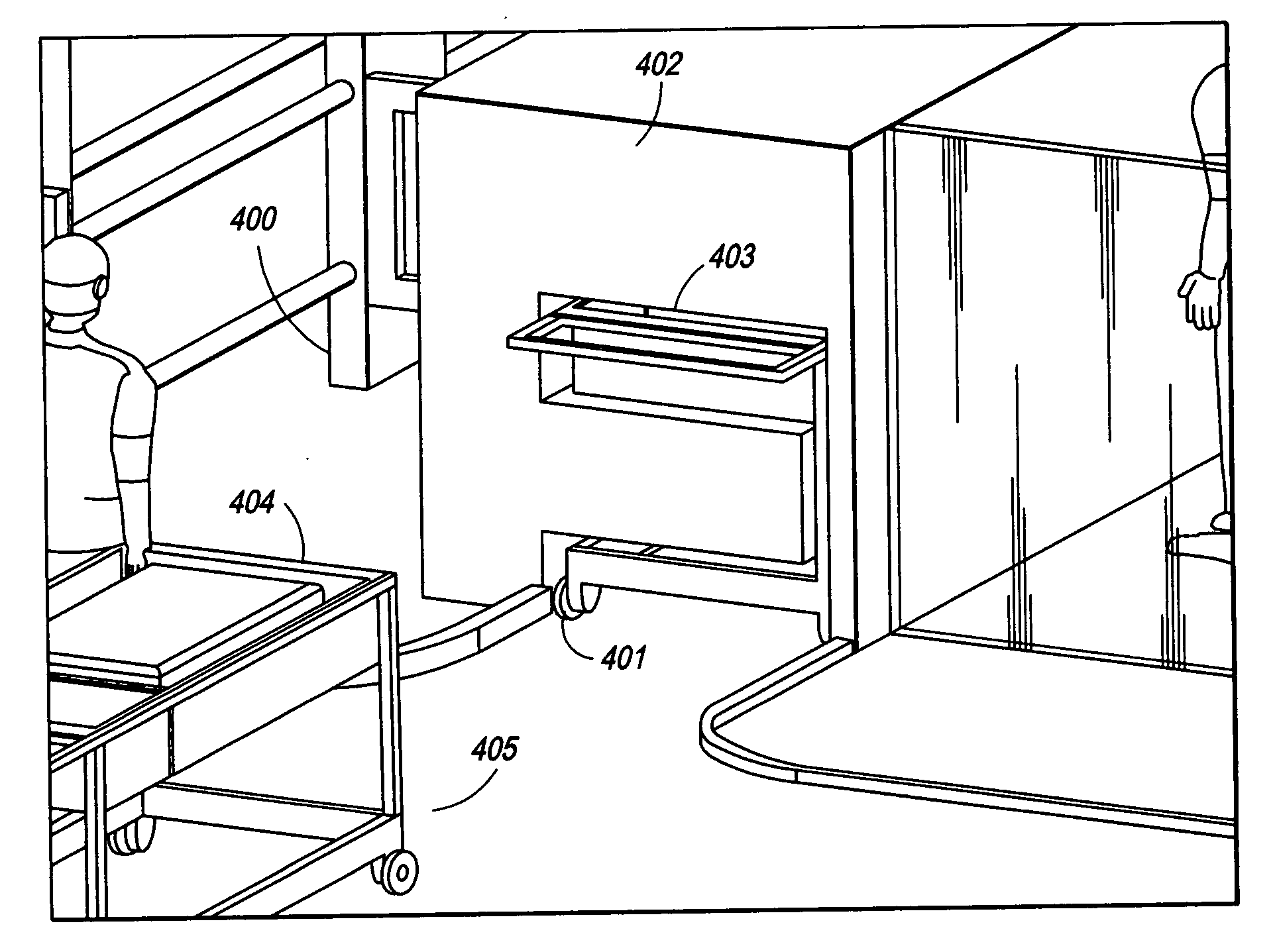
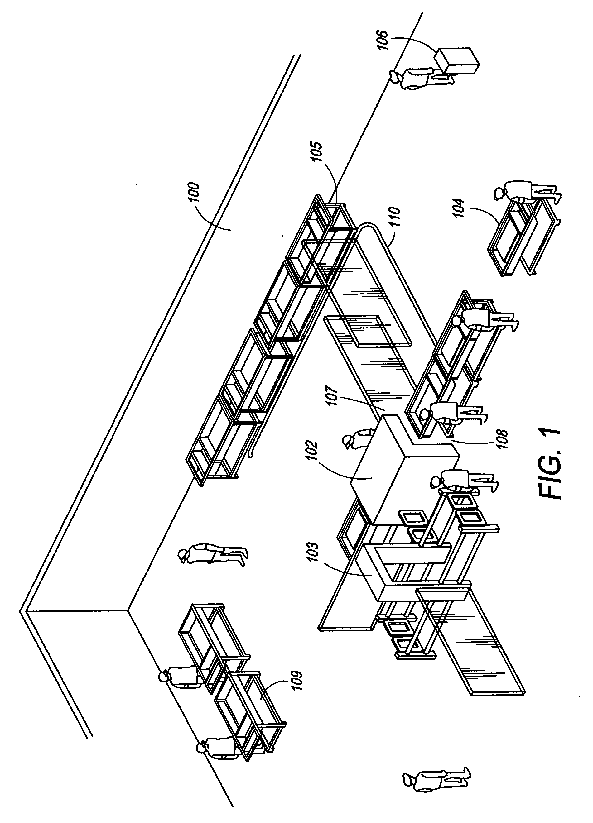
[0026] The present invention is directed toward an integrated security checkpoint that can screen both individual passengers and carry-on carts containing their baggage. The methods, apparatuses, and systems of the present invention enable the efficient scanning of both individual passengers and their respective carry-on carts in the same secure area by providing individual passengers with a screening cart, permitting passengers to send the screening cart through an X-ray imaging machine, and permitting passengers to walk through an adjacent metal detector where, once cleared, the individual passenger can retrieve his or her screening cart.

Problems solved by technology

It takes a considerable amount of time for individuals to divest themselves of their belongings and to remove laptops from their cases.
The conventional prior art security baggage and passenger screening systems described above are inefficient in the manner in which they are set up to receive and distribute both passengers and their carry-on baggage.
It takes a considerable amount of time for individuals to divest themselves of these belongings.
Thus, X-ray machine operators spend more time waiting for passengers to divest themselves of their belongings and load them onto the conveyor than scanning bags.
Thus, the bags are left on the conveyor for approximately at least 1.5-2.0 minutes, thereby causing a back-up that forces the X-ray machine operator to have to wait until such back-up is cleared.
Thus, even when individual passengers have access to the machine, the process is still time-consuming as each individual item to be scanned must be placed on the single conveyor belt and then collected by the owner.
This is especially true for Computerized Tomography (CT) scanning systems, which are much slower in operation compared with conventional X-ray scanning systems.
In addition to the time it takes for the machine to operate, it may take some time for a passenger to reclaim and collect his baggage and other personal belongings, further creating a backlog in the scanning system.
In addition, such existing systems tend to have many other problems, including for example, several security personnel having excessive downtime and a necessity for a dedicated operator for each detector to direct traffic.
Additionally, passengers lack sufficient information regarding how to most efficiently pass through a baggage checkpoint or screening station.
For example, passengers may wait in a screening station or checkpoint lane full of passengers while a second lane remains completely empty, thereby causing unnecessary delay.
Thus, the much desired streamlined and efficient function of the scanning operation is hampered.
Current systems lack appropriate means for indicating whether lanes, among a plurality of check station lanes, are operational or closed.
Furthermore, passengers lack information regarding what items should be subjected to CT scanning, x-ray scanning, metal detection, or hand searching, such as large buckle belts or shoes.
The presence of portable computing devices, such as laptops, further causes more delay.
It takes a considerable amount of time for individuals to remove laptops from their cases.
Passengers often fail to efficiently remove such items from their carrying cases and, consequently, do not proceed through the scanning checkpoint efficiently.
Additionally, those areas contained within the scanning checkpoint or check station areas specifically allocated for passengers to divest themselves of their belongings are not set up to facilitate rapid and efficient divestiture of passenger belongings.
Along the same lines, the problem also presents itself when passengers collect their belongings and reload their items and replace portable computing devices in their cases.
Individual passengers also lack proper instruction on where to stand so as not to obstruct the natural flow of the X-ray scanning system line.
Conventional security screening systems lack appropriate means for handling carry-on baggage in its entirety prior to and / or during scanning.
Traditional carry-on baggage carts are cumbersome and bulky in dimension, including towable, portable, or mobile carts.
These carry-on baggage carts present problems when scanned in conventional scanning systems.
For example, the design of the carts does not allow for conventional scanning systems to sufficiently scan due to the inadequate positioning of the carry-on baggage.
This, in turn, leads to the capturing, storing, processing and development of incomplete and imprecise X-ray images.
Metal bars of existing cart designs may also hinder the path of the X-ray, thus obscuring some of the items placed on the cart from scanning.
This also leads to imprecise capturing, storing, processing and development of x-ray images.
In addition, in scanning conventionally designed carry-on baggage carts, it is difficult to contain the x-ray radiation; to scan an existing, conventional carry-on baggage cart, the x-ray machine would need a large opening.
Thus, in such systems, costly safeguards would need to be implemented to protect the general public and x-ray operators.
Despite these prior art efforts to improve methods, apparatuses, and systems for scanning carry-on baggage, the above mentioned problems have not been solved.
The prior art methods fail to disclose methods and systems that alleviate delay during the divestiture process.
In addition, the prior art does not improve the overall efficiency and throughput of the system.

Method used


Image

  • Integrated carry-on baggage cart and passenger screening station
  • Integrated carry-on baggage cart and passenger screening station
  • Integrated carry-on baggage cart and passenger screening station

Examples


second embodiment

[0107] In another embodiment of the integrated carry-on baggage cart and passenger screening station, facilitating screening of both carry-on luggage placed on the screening cart and individual passengers, a computed tomography (CT) scanner is employed. Thus, the corresponding carry-on baggage cart is designed to facilitate screening via non-“C” shaped scanners, such as, but not limited to CT scanners. In addition, the corresponding carry-on baggage cart is X-ray transmissive to allow for the CT scanner system to scan completely around the cart. While the second embodiment is described with respect to an integrated carry-on baggage cart and passenger screening station in which a CT scanner is employed, it is to be understood by those of ordinary skill in the art that this invention is not limited to such uses, but that any scanning device or mechanism may be used.

[0108] CT scanners are being increasingly deployed for securing locations such as airports, as they more accurately recog...

first embodiment

[0120] In an alternate embodiment, the entrance of the CT scanning system may be designed such that the inlet to the scanning chamber is at floor level. In this embodiment, a guide-rail mechanism may be used to pull the cart into the scanner entrance, as previously described with respect to the present invention.

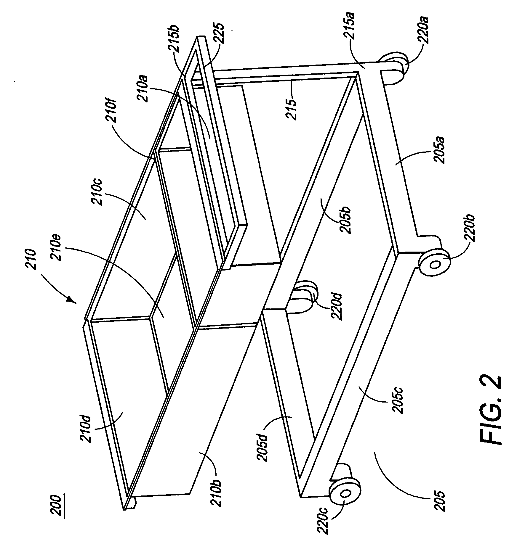
[0121] Preferably, the carry-on baggage cart is designed to allow for the carts to be stacked or inserted into one another when not in use. This provides for easy and space-saving storage of carts.

[0122] As previously mentioned, the process of CT scanning involves a complete circumferential (360°) rotation by the illuminating source and detectors about the object under inspection. In order to allow irradiation and imaging from all angles, the carry-on baggage cart is designed to be completely X-ray transmissive. Preferably, the entire cart, including legs, wheels, and handle is manufactured using a suitable X-ray transmissive material or combination thereof. Such X-ray tran...


PUM


Abstract

The present invention is directed towards apparatuses and methods for securing a location. Particularly, the present invention is directed towards methods, apparatuses, and integrated systems for the screening of individual passengers and their corresponding carry-on baggage carts with improved throughput, efficiency, and quality. In addition, the current invention is directed towards a carry-on baggage cart specifically designed for the disclosed integrated carry-on baggage cart and passenger screening system of the present invention.

Description

CROSS-REFERENCE TO RELATED APPLICATIONS [0001] The present invention is a continuation-in-part of U.S. patent application Ser. No. 11 / 032,314, filed on Jan. 10, 2005. FIELD OF THE INVENTION [0002] The present invention relates to an apparatus for, and a method of, securing a location. More specifically, the present invention is a method, apparatus, and integrated system for screening of individual passengers and their corresponding carry-on baggage carts with improved throughput, efficiency, and quality. The present invention also relates to a carry-on baggage cart specifically designed for the disclosed integrated carry-on baggage cart and passenger screening system. BACKGROUND OF THE INVENTION [0003] Locations must often be secured to ensure public safety and welfare. For example, places where there are large concentrations of people, such as airports or entertainment events, places that are of particular governmental importance, such as courthouses and government buildings, and o...

Claims


Application Information

Patent Timeline
IPC IPC(8): G01N23/04
CPCG01V5/0008G01N23/04G01V5/20
Inventor GRAY, STEPHEN J.
Owner RAPISCAN SYST INC (US)
Learn More