
Apparatus, system, and methods for status monitoring and control of cable television network components

a technology of status monitoring and control, applied in the field of communication transmission networks, can solve the problems of being only needed, and the cost is typically more expensive, and achieve the effect of cost-effective monitoring and control

Inactive Publication Date: 2007-01-04
AM NETWORKS
View PDF2 Cites 13 Cited by
  • Summary
  • Abstract
  • Description
  • Claims
  • Application Information

AI Technical Summary

Benefits of technology

"The present invention provides a cost-effective way to monitor and control distributed devices in a cable television network. It introduces a gateway transponder and a device transponder, which allows for efficient communication between a network operator management system and a set of device transponders. The gateway transponder simplifies the management protocol and reduces the size of management messages exchanged between the gateway and the device transponder. This invention eliminates the need for expensive and complex proprietary monitoring system headend controllers and allows network operators to deploy more cost-effective technology only where needed."

Problems solved by technology

Thereby, enabling network operators to deploy DOCSIS hardware and technology—which is typically more expensive and complex—only where needed.

Method used


Image

  • Apparatus, system, and methods for status monitoring and control of cable television network components
  • Apparatus, system, and methods for status monitoring and control of cable television network components
  • Apparatus, system, and methods for status monitoring and control of cable television network components

Examples


Embodiment Construction

[0023] While the present invention is described herein with reference to illustrative embodiments for particular applications, it should be understood that the invention is not limited thereto. Those skilled in the art with access to the teachings provided herein will recognize additional modifications, applications, and embodiments within the scope thereof and additional fields in which the present invention would be of significant utility.

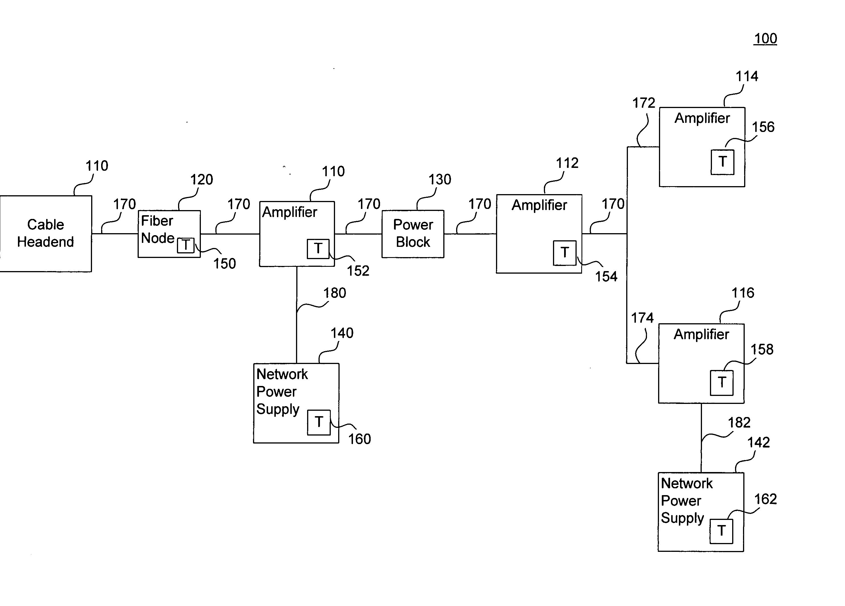
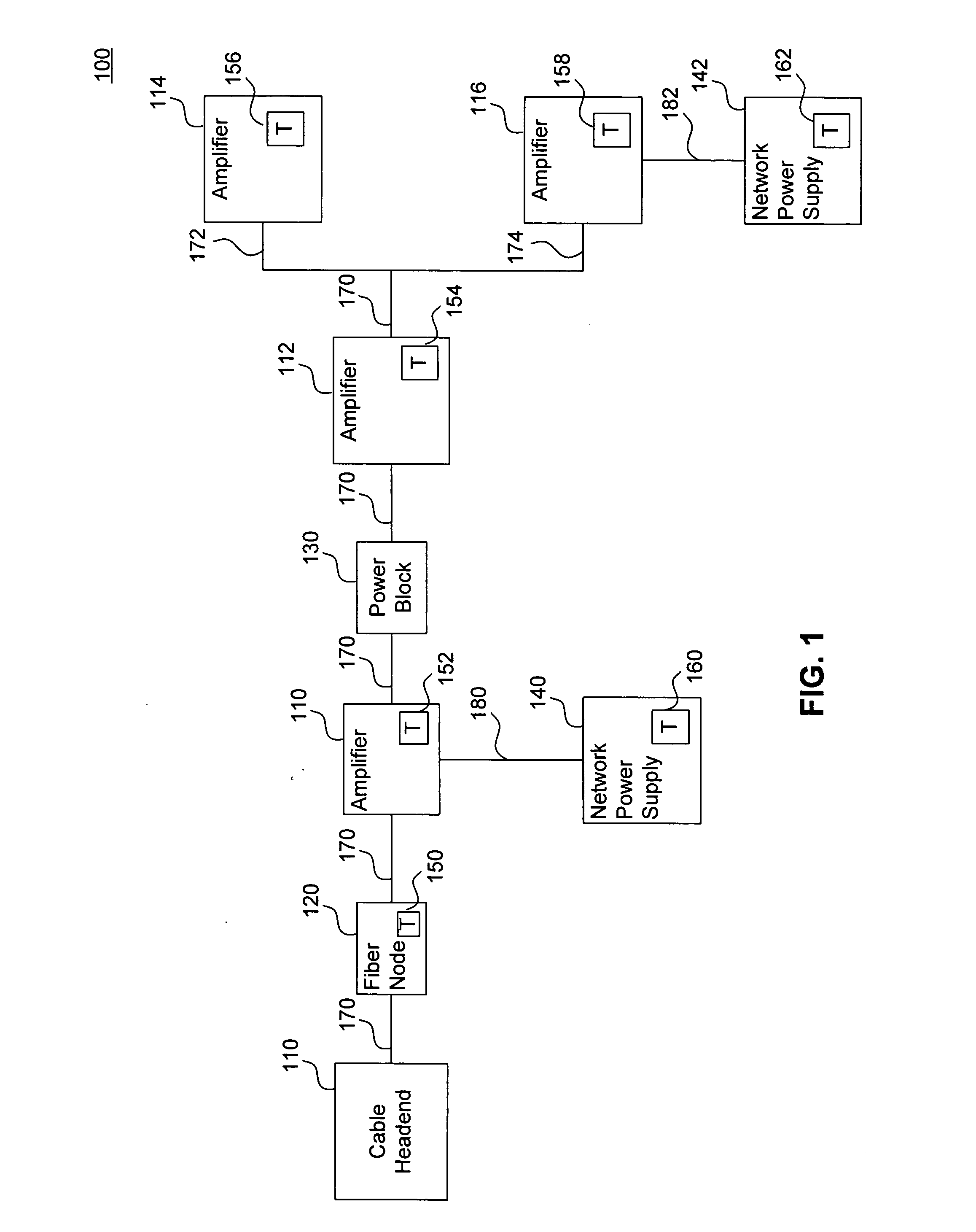
[0024]FIG. 1 illustrates a portion of a typical cable television network. The example cable television network portion shown consists of cable headend 110, fiber node 120; amplifiers 110, 112, 114 and 116; network power supplies 140 and 142 and power block 130. Additional devices, such as splitters, taps and additional feeder distribution networks to customer premises are not illustrated for simplicity. A cable television signal can be transmitted over fiber optic cable 170 through the devices to multiple end user subscribers (not shown).

[0025]...


PUM


Abstract

Apparatus, systems, and methods to cost effectively monitor and control distributed devices within a cable television network are disclosed. In particular, a gateway transponder and a device transponder are provided. A device transponder can be associated with a device other than a power supply located in a cable television network. The device transponder provides an efficient mechanism for exchanging control messages between a device where the transponder resides and a network operator management system. A gateway transponder can be associated with a network power supply. A gateway transponder serves as a gateway between a network operator management system and a set of device transponders. In a further feature of the present invention, a very simplified management protocol is provided that simplifies Simple Network Management Protocol (SNMP) messaging and reduces the size of management messages that are exchanged between a gateway transponder and a device transponder.

Description

CROSS REFERENCE TO RELATED APPLICATIONS [0001] The present application claims the benefit of the filing dates of U.S. Provisional Patent Application No. 60 / 564,230, filed Apr. 22, 2004, which is incorporated by reference herein in its entirety.BACKGROUND OF THE INVENTION [0002] 1. Field of Invention [0003] The present invention relates to communication transmission networks, and more particularly to cable television transmission networks. [0004] 2. Related Art [0005] In a cable television transmission network, radio frequency signals are transmitted bi-directionally between a plurality of subscriber premises and a central headend facility. The bi-directional capability is achieved using a frequency division multiplexing method wherein signals higher than approximately 50 MHz propagate toward subscriber homes and signals lower than approximately 40 MHz propagate toward the headend. These transmission networks commonly employ a hybrid fiber-coax (HFC) architecture, with fiber optic ca...

Claims


Application Information

Patent Timeline
Patent Type & Authority Applications(United States)
IPC IPC(8): H04L12/56H04L12/66
CPCH04L12/2801H04L41/0213H04L43/0817H04N7/17309H04N21/25808H04N21/818H04N21/6118H04N21/6168H04N21/643H04N21/64322H04N21/64753H04N21/40
Inventor ROCCI, JOSEPH D.QUELLY, MICHAEL L.
Owner AM NETWORKS
Learn More