
Electrically illuminated flame simulator

a flame simulator and electric light technology, applied in semiconductor devices, light sources, power sources, etc., can solve the problems of inability to easily control electronically, inherently produce unnatural flickering patterns that may not be easily controlled, and are generally unsuitable for battery operation

Inactive Publication Date: 2007-01-04
LIU MONITA
View PDF7 Cites 75 Cited by
  • Summary
  • Abstract
  • Description
  • Claims
  • Application Information

AI Technical Summary

Benefits of technology

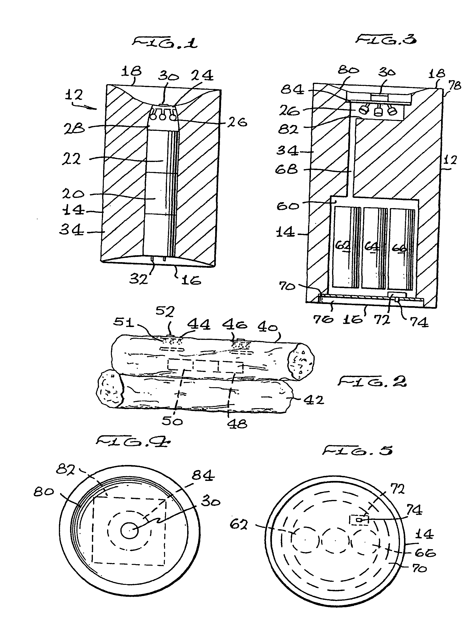
[0011] According to another aspect of the invention, the flame simulator may also be used to provide an effect similar to that of a candle when used in a fake fire log intended to produce the effect of a natural burning log.
[0022] According to another aspect of the invention, there is provided a candle having an electrically powered flame simulator comprising: a candle body having an upper portion, a lower portion and a chamber therein; and a flame simulator having at least two light sources located near the upper portion of the candle body, an integrated circuit within the candle body and electrically connected to the light sources for intermittently, such as by randomly or semi-randomly, illuminating at least one of the light sources independently of other light sources such that the light sources together provide the effect of a flickering movement, and a power source in the chamber of the candle body for providing power to the integrated circuit.

Problems solved by technology

There are, of course, natural hazards associated with such a device, since they may result in fire accidents which, if unattended or not properly controlled, can produce extensive damage, smoke or pollution.
Such unstable neon bulbs, however, inherently produce an unnatural “jerky” flickering pattern that may not be easily controlled electronically, and must be operated by high voltage sources.
At the least, this makes them generally unsuitable for battery operation.
Such incandescent light bulbs, however, are inherently limited in terms of flickering rate and effect due to retention of filament heat, and draw substantially more current than solid state light sources such as LED lights.
Once more, this is not generally suitable for battery operation, at the least.
Certainly, the effect produced by these linear arrays does not mimic the illusion of a flickering flame.

Method used


Image

  • Electrically illuminated flame simulator
  • Electrically illuminated flame simulator
  • Electrically illuminated flame simulator

Examples


Embodiment Construction

[0035] The invention is for a flame simulator which is powered electrically, and comprises a series of bulbs or LEDs which are illuminated randomly, semi-randomly or in a predetermined a manner to provide the visual effect of a flickering flame. The device is preferably coupled to an ornament such as a candle or fire log to enhance this effect.

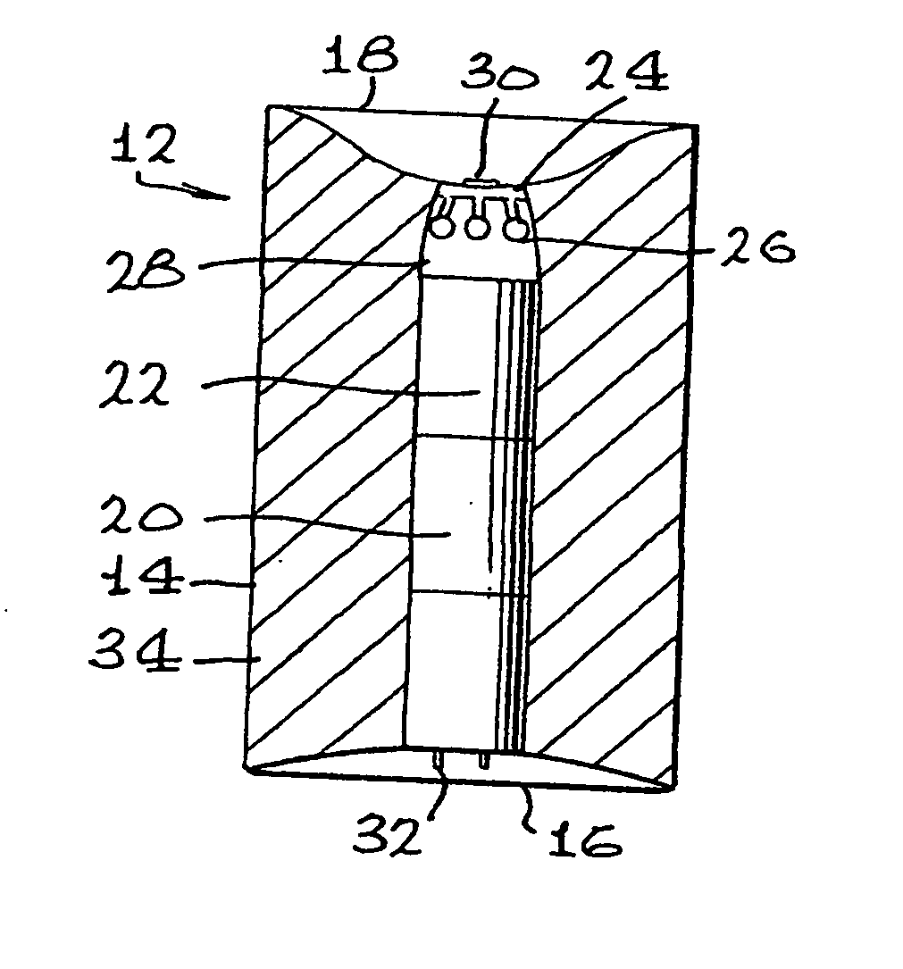
[0036]FIG. 1 of the drawings shows schematically a candle 12, generally of cylindrical shape having side wall 14, a base 16, and a top surface 18. The candle 12 comprises a hollowed out central portion 20, generally extending between the top surface 18 and the base 16, which, in the embodiment of FIG. 1, may accommodate a power source such as batteries 22. Near the top surface 18 there is located circuitry 24, the circuitry 24 being connected to LED light sources 26, four of which are shown in the embodiment in FIG. 1 of the drawings. The LED light sources 26 open into a chamber 28, generally formed between the top of the batteries 22 and the...


PUM


Abstract

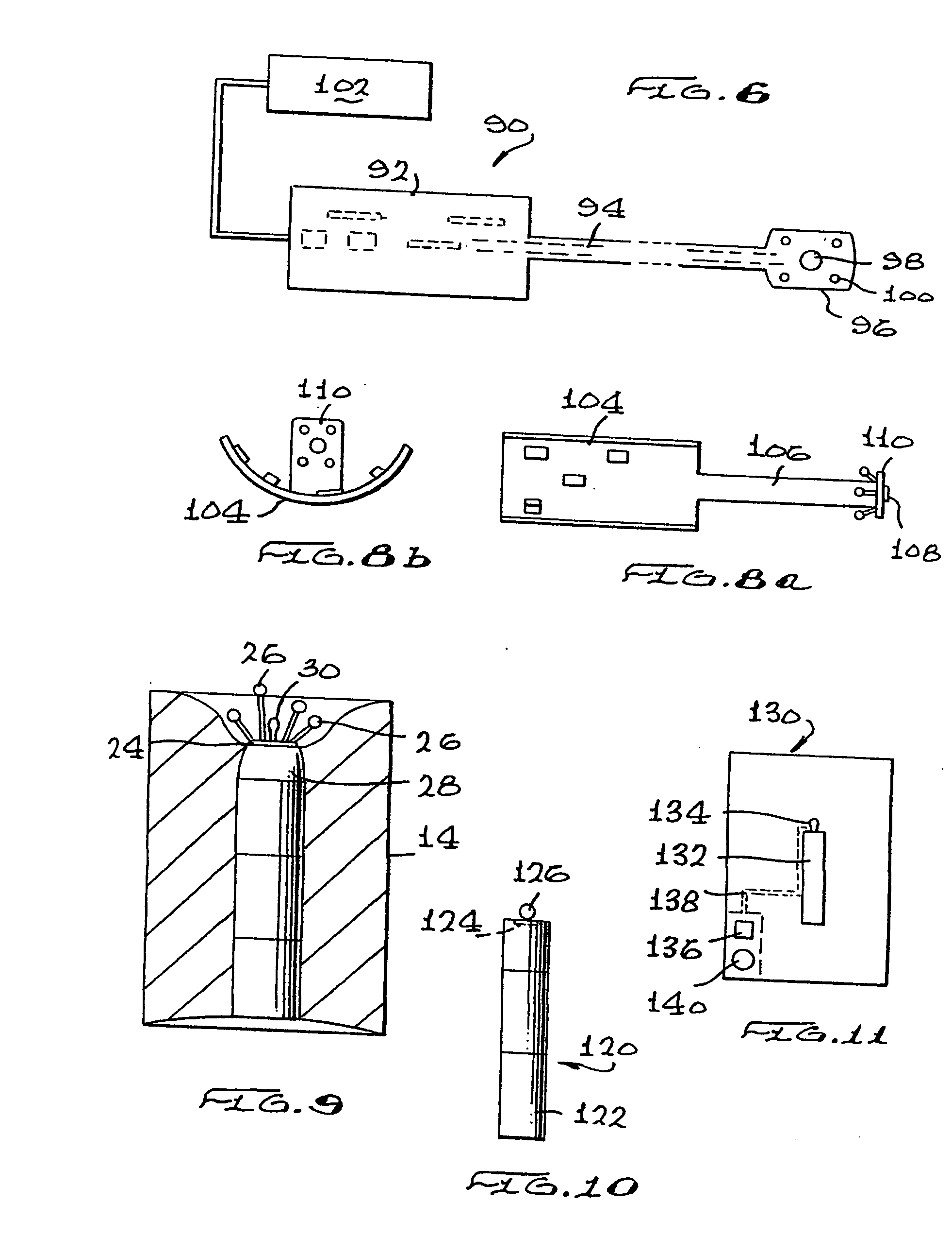
An electrically powered flame simulator comprises at least two light sources, an integrated circuit electrically connected to the light sources for intermittently illuminating at least one of the light sources independently of other light sources such that the light sources together provide the effect of a flickering movement, and a power source for providing power to the integrated circuit. The flame simulator may be mounted in a decorative or ornamental device such as a candle or fire log, or used on decorative clothing, or may be part of a hazzard or warning system. One or more solid state light sources may also be used.

Description

CROSS REFERENCE TO RELATED APPLICATIONS [0001] This application is a continuation application of U.S. patent application Ser. No. 10 / 822,392 filed Apr. 12, 2004, which is a continuation application of U.S. patent application Ser. No. 10 / 084,272 filed Feb. 27, 2002, which is incorporated herein by reference in its entirety.FIELD AND BACKGROUND OF THE INVENTION [0002] This invention relates to an electrically illuminated flame simulator. Particularly, the invention relates to decorative candles, fire logs, or other devices which may be illuminated so as to produce a flickering flame effect. The flame simulator of the invention would typically be electrically powered by batteries, either disposable or rechargeable, but may also be powered through a regular AC outlet, with or without an AC adaptor. [0003] Candles, fire logs, specially created street lights and other devices which may be used, for example, on clothing, cycles or other products are commonly available and valued for their ...

Claims


Application Information

Patent Timeline
IPC IPC(8): F21V35/00F21S4/00F21S9/02F21S10/04F21V23/04H05B37/02H05B44/00
CPCF21S6/001H05B33/0854F21S10/04F21V23/0442F21Y2101/02H05B33/0845H05B37/0236F21V35/00H04R1/028F21W2121/00Y10S362/80Y10S362/81Y10S362/812F21V33/0028F21S9/022F21Y2115/10H05B47/12Y02B20/40H05B47/10H05B45/12F21S9/02F21V23/04F21V23/06
Inventor GUTSTEIN, ROBERT A.LIU, MONITA
Owner LIU MONITA
Learn More