Gauge tee device
a tee device and gauging technology, applied in the direction of fluid pressure measurement, branching pipes, instruments, etc., can solve the problems of limited use of disposable devices, low flow rate and small tubing sizes, and inability to reliably and low cost systems developed for disposable us
- Summary
- Abstract
- Description
- Claims
- Application Information
AI Technical Summary
Benefits of technology
Problems solved by technology
Method used
Image
Examples
first embodiment
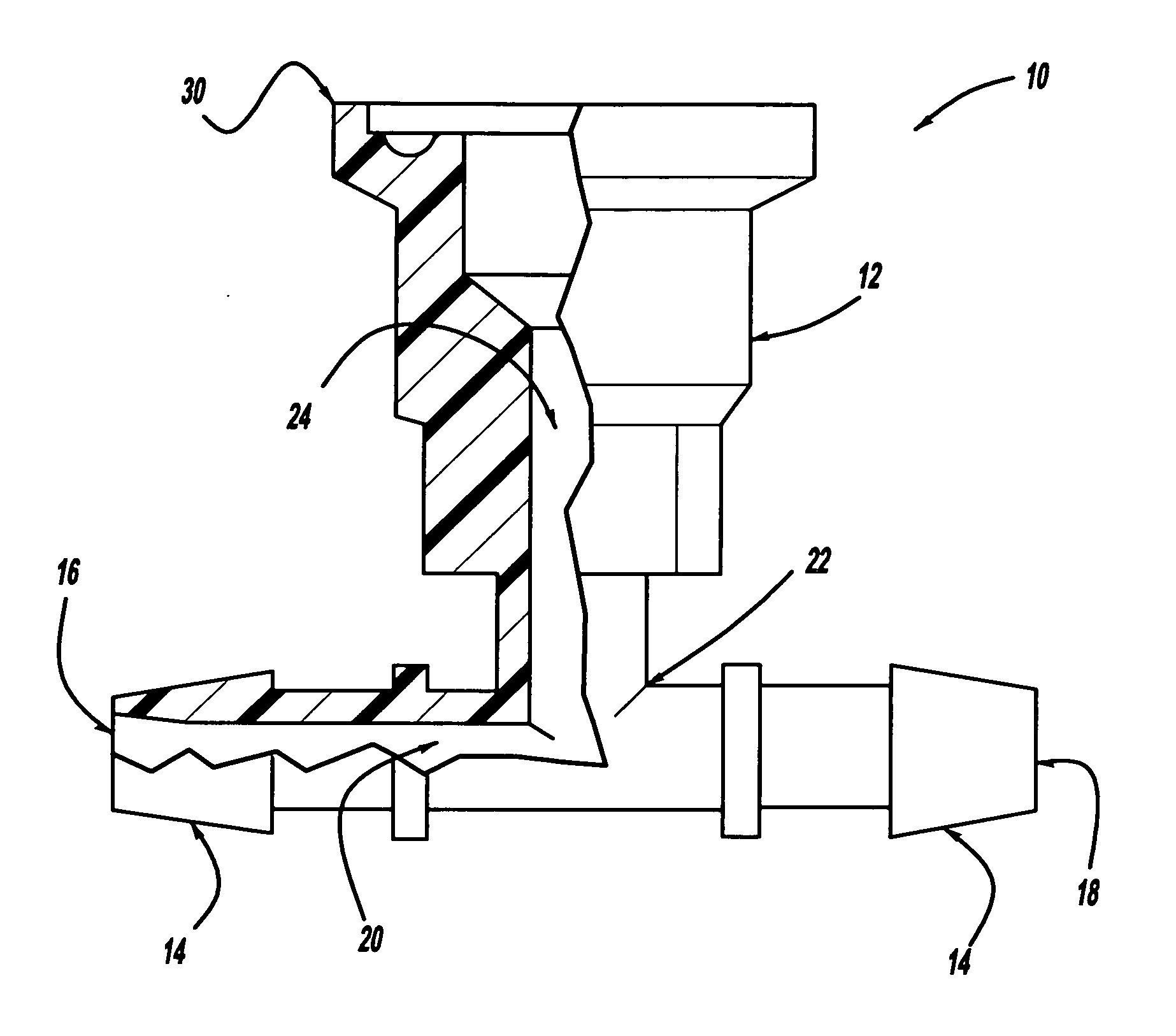
[0035] The present invention has numerous advantages over the prior art. There are very few other ways to measure pressure in disposable tubing other than pressure sensors with attached hose barbs and a digital readout. The present invention provides minimal hold-up volume by utilizing a cup-like design of the pressure fluid passageway, as described below. It can be used in disposable filtration systems for biopharmaceuticals or other liquids. For example, the present invention allows for accurate pressure monitoring of liquids in disposable tubing during bioprocess filtration, chromatography, or other pressure controlled processes. Since the gauge tee device 10 of the present invention can be sterilized, it can be utilized for disposable tubing and bag systems and allows for aseptic pressure monitoring of a process. The gauge tee device 10 of the present invention is disposable, which eliminates the need for cleaning or cleaning validation since it is used only one time (a great be...
second embodiment
[0042] the gauge tee device 10′ is shown in FIGS. 6 and 7 of a ¾ inch disposable sanitary gauge tee including compression fittings 40′ that can accommodate ¼ inch inner diameter or ⅜ inch inner diameter disposable tubing 32. This gauge tee device 10′ allows pressure to be monitored during fluid processing in disposable tubing. Further, the compression fitting 40′ allows for use in systems and / or processes that exert greater than 15 psid. The gauge tee device 10′ includes a sanitary gauge tee body 12′ in operative connection with compression fittings 14′. A first fluid port 16′ is in fluid connection with a second fluid port 18′ at each compression fitting 14′ through a main fluid passageway 20′. The main fluid passageway 20′ is also in fluid connection with a proximal end 22′ of a pressure fluid passageway 24′. A biocompatible gauge protector 26 and a sanitary pressure gauge 28 can be removably attached to a distal end 30′ of the pressure fluid passageway 24′ in order to measure the...
third embodiment
[0044] In use, the gauge tee device 10, 10′, 10″ can be hooked up to a line of tubing 32 in order to measure the pressure of the fluid within that line. The tubing 32 is attached at the hose barbs 14, 14′, 14″ and can be secured by the securing device 34 or compression fittings 40′. The biocompatible gauge protector 26 is placed over the distal end 30, 30′, 30″ of the pressure fluid passageway 24, 24′, 24″ to protect the fluid from the metal of the sanitary pressure gauge 28. The sanitary pressure gauge 28 is next attached to the 30, 30′, 30″ of the pressure fluid passageway 24, 24′, 24″ and can be secured by the sanitary clamp 38. Fluid is then flowed through the tubing 32 and the pressure of the fluid is monitored by the sanitary pressure gauge 28. Fluid flowing up the pressure fluid passageway 24″ in the third embodiment also flows completely out because of the cup-like design, ensuring that no fluid remains to contaminate the process.
[0045] In another embodiment of the present i...
PUM
 Abstract
Description
Claims
Application Information
 - R&D
- Intellectual Property
- Life Sciences
- Materials
- Tech Scout
- Unparalleled Data Quality
- Higher Quality Content
- 60% Fewer Hallucinations
Browse by: Latest US Patents, China's latest patents, Technical Efficacy Thesaurus, Application Domain, Technology Topic, Popular Technical Reports.
© 2025 PatSnap. All rights reserved.Legal|Privacy policy|Modern Slavery Act Transparency Statement|Sitemap|About US| Contact US: help@patsnap.com


