
Sensor baseline compensation in a force-based touch device

a touch device and baseline compensation technology, applied in the direction of instruments, speed measurement using gyroscopic effects, liquid/fluent solid measurement, etc., can solve the problems of non-zero output of force sensors, baseline error drift in quiescent output of sensors, complex determination of etc., to achieve the effect of improving the accuracy of determining the location and magnitude of applied for

Inactive Publication Date: 2006-12-28
QSI CORPORATION
View PDF62 Cites 146 Cited by
  • Summary
  • Abstract
  • Description
  • Claims
  • Application Information

AI Technical Summary

Benefits of technology

[0007] In light of the problems and deficiencies inherent in the prior art, the present invention seeks to overcome these by providing compensation for a force-based input device that can enhance the accuracy in determining the location and magnitude of an applied force.

Problems solved by technology

Determining the location and magnitude of the applied force is complicated by errors in the output from the force sensors.
Baseline error is drift in the quiescent output of the sensors, for example due to environmental effects.
For example, stresses on the force sensors due to the weight of the touch surface and / or preload forces that are applied during manufacture can result in non-zero output from the force sensors.
Moreover, baseline output tends drift with time due to aging, temperature, and other factors.
In particular, the determination of touch location can be extremely sensitive to baseline errors.
This is because baseline errors can result in a constant bias in the formulas used to calculate the touch location.
For example, baseline errors which appear in denominator terms tend to cause error in scale that varies with the applied force.
Distinguishing between periods of touch activity and no-touch activity can, however, be difficult.
For example, light touches are difficult to distinguish from baseline variations.

Method used


Image

  • Sensor baseline compensation in a force-based touch device
  • Sensor baseline compensation in a force-based touch device
  • Sensor baseline compensation in a force-based touch device

Examples


Embodiment Construction

[0017] The following detailed description of exemplary embodiments of the invention makes reference to the accompanying drawings, which form a part hereof and in which are shown, by way of illustration, exemplary embodiments in which the invention may be practiced. While these exemplary embodiments are described in sufficient detail to enable those skilled in the art practice the invention, it should be understood that other embodiments may be realized and that various changes to the invention may be made without departing from the spirit and scope of the present invention. Thus, the following more detailed description of the embodiments of the present invention is not intended to limit the scope of the invention, as claimed, but is presented for purposes of illustration only and not limitation to describe the features and characteristics of the present invention, to set forth the best mode of operation of the invention, and to sufficiently enable one skilled in the art to practice ...


PUM


Abstract

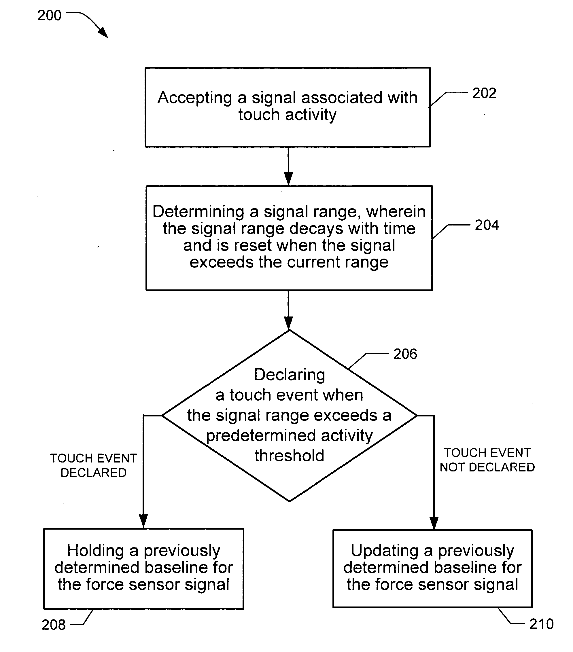
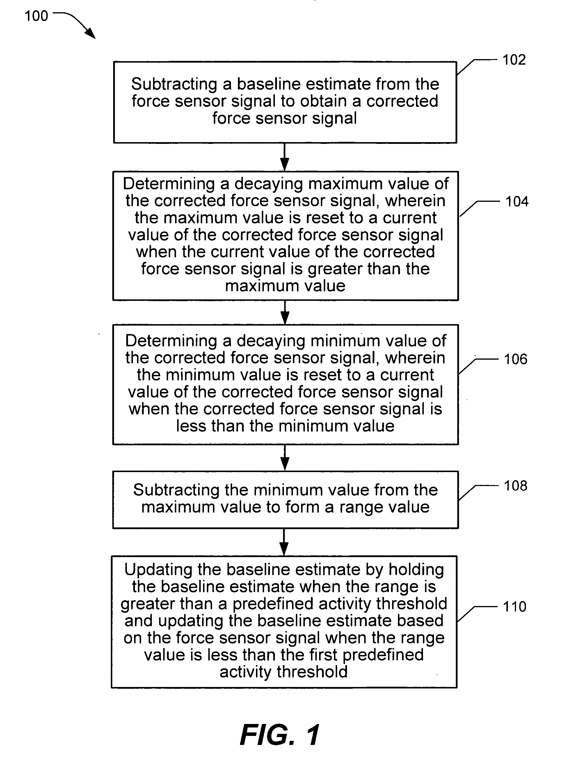
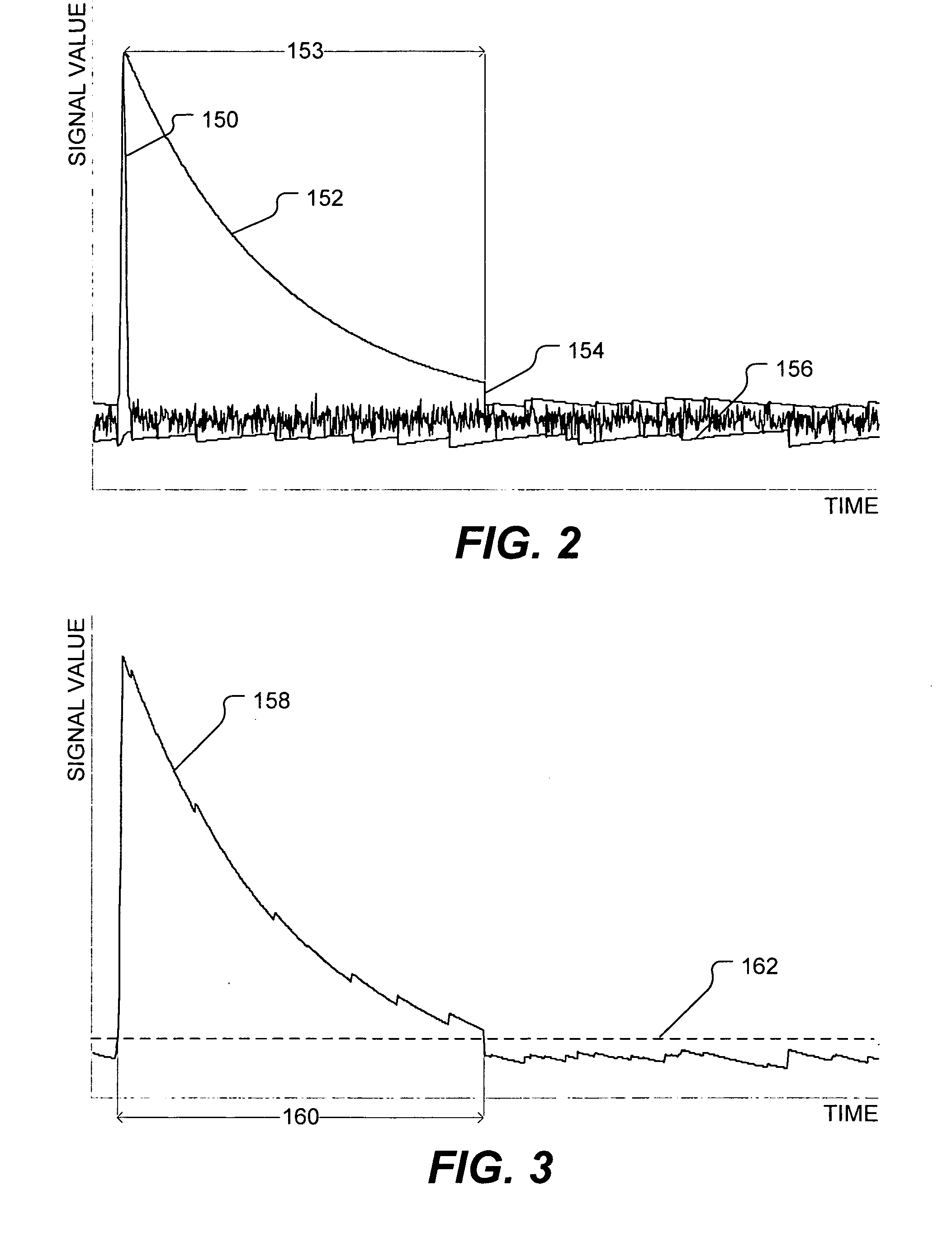
Disclosed is method and device for compensating a force sensor signal for baseline error in a force-based touch screen. In one embodiment, baseline compensation includes determining a decaying maximum value and a decaying minimum value of the force sensor signal, and subtracting these values to obtain a range value. When the range value is less than a predetermined activity threshold, updating of the baseline is disabled. The decaying maximum value and decaying minimum value are reset to the current value of the force sensor signal when exceeded by the current value of the force sensor signal.

Description

CROSS REFERENCE TO RELATED APPLICATIONS [0001] This application claims the benefit of U.S. Provisional Patent Application Ser. No. 60 / 708,867 filed Aug. 16, 2005, entitled “Force-Based Input Device” and U.S. Provisional Patent Application Ser. No. 60 / 689,731 filed Jun. 10, 2005, entitled “Signal Conditioning in a Force-Based Touch Device,” each of which is hereby incorporated by reference in their entirety for all purposes.FIELD OF THE INVENTION [0002] The present invention relates generally to force-based input devices, and more particularly to sensor baseline compensation in force-based input devices, wherein signals from force sensors in the force-based input device are processed to obtain specific characteristics about or related to an applied force, such as its location and magnitude. BACKGROUND OF THE INVENTION AND RELATED ART [0003] Input devices (e.g., a touch screen or touch pad) are designed to detect the application of an object and to determine one or more specific chara...

Claims


Application Information

Patent Timeline
Patent Type & Authority Applications(United States)
IPC IPC(8): G06F19/00
CPCG06F3/0418G06F3/0414G06F3/04144
Inventor SOSS, DAVID A.
Owner QSI CORPORATION
Learn More