Desanding apparatus and system

a technology of desanding apparatus and system, which is applied in the direction of liquid displacement, separation process, borehole/well accessories, etc., can solve the problems of dropping the velocity of the fluid stream and the inability to maintain the suspension of particulates

Inactive Publication Date: 2006-12-28
SPECIALIZED DESANDERS
View PDF59 Cites 2 Cited by
  • Summary
  • Abstract
  • Description
  • Claims
  • Application Information

AI Technical Summary

Problems solved by technology

As a result, fluid stream velocity drops and particulates cannot be maintained in suspension.

Method used


Image

  • Desanding apparatus and system
  • Desanding apparatus and system
  • Desanding apparatus and system

Examples


examples

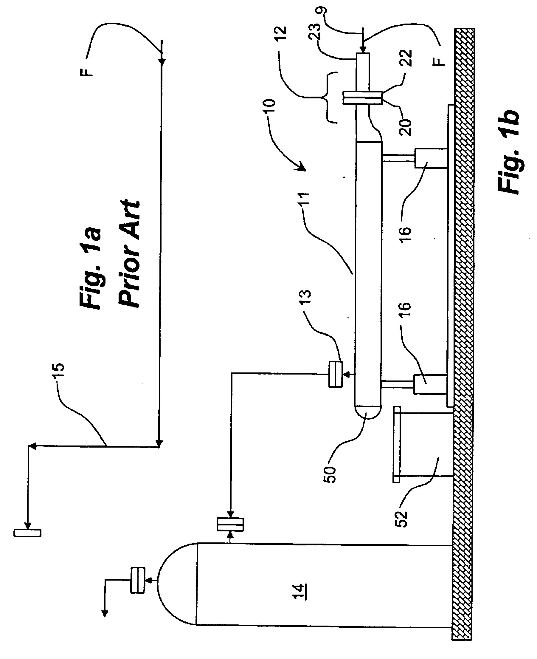
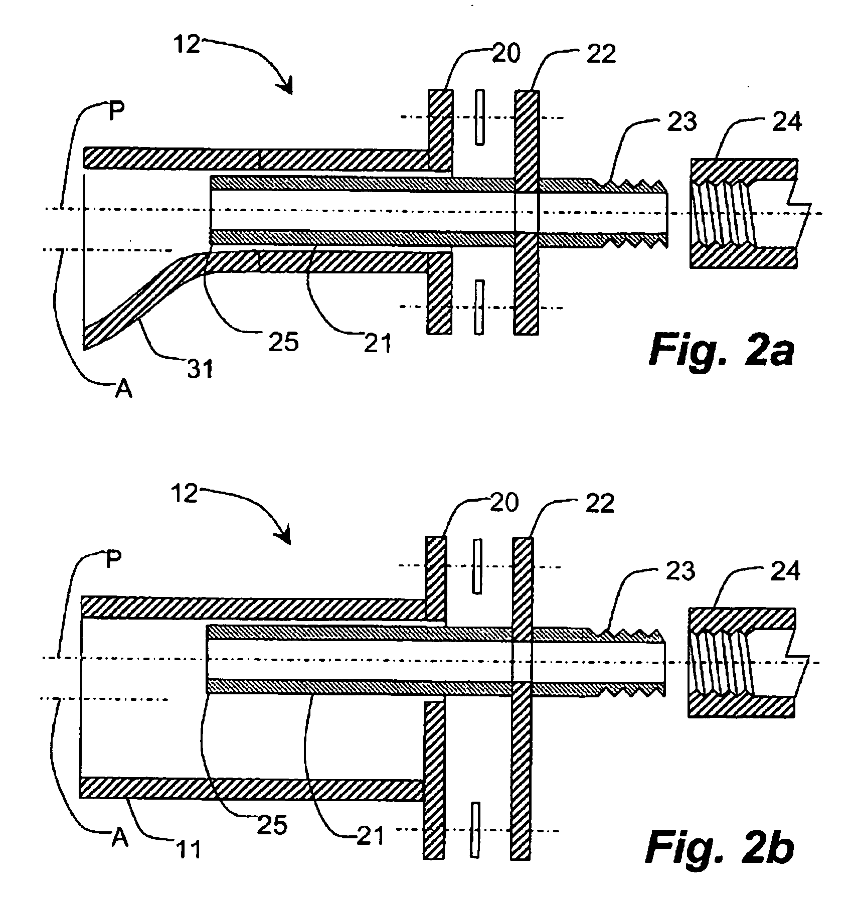
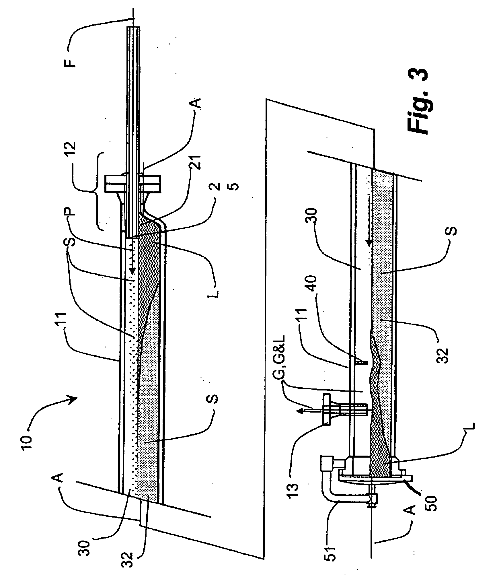
[0033] A typical vessel according to the present invention, and for reference are roughly approximated by the proportions of FIG. 3, can be a 6″ or an 8″ diameter. Using an 8″ diameter, schedule 160 shell for the vessel 11 can result in a fluid stream capacity of about 8 million cubic feet of gas per day. A 2″ schedule 160 inlet nozzle extends about 1″ beyond an eccentric inlet 12 and into the vessel 11. With a flow barrier 40 placed about 8 feet from the nozzle discharge 25, the desander 10 achieved a corresponding and typical collection rate of 1.5 gallons of sand particulates per day, determined in a worst case scenario of particles of about 100 mesh. Applied to problem wells in several exceptional cases, using no vessel at all, one prior art wellhead, piping and equipment experienced four breaches and in another case, seven breaches. After installation of a preferred vessel of the present invention, no further breaches were experienced. In one case, the resulting collection of p...


PUM

PropertyMeasurementUnit
diameteraaaaaaaaaa
diameteraaaaaaaaaa
velocityaaaaaaaaaa

Abstract

A desanding vessel is inserted in a high velocity fluid stream containing entrained particulates. The vessel comprises an upper freeboard portion having a large cross-sectional wherein the fluid stream velocity drops and particulates fall from suspension. Preferably the fluid stream is introduced offset upwardly from an axis of a horizontally oriented cylindrical vessel, released particulates falling to accumulate in a lower belly portion. The freeboard portion is maintained using a depending flow barrier adjacent the vessel's outlet which sets the depth of accumulation in the belly portion. A cleanout enables periodic removal of accumulations.

Description

CROSS REFERENCE TO RELATED APPLICATION [0001] This application is a divisional application of U.S. application Ser. No. 10 / 668,266 filed Sep. 24, 2003 and claiming priority of U.S. Provisional application 60 / 417,146 filed Oct. 10, 2002 and of prior foreign applications namely, Canadian Patent Application 2,407,554 filed Oct. 10, 2002 and Canadian Patent Application 2,433,741 filed Jun. 27, 2003.FIELD OF THE INVENTION [0002] The present invention relates to a system and apparatus for the removal of particulates such as sand from fluid streams produced from a well while minimizing abrasion of the involved equipment. BACKGROUND OF THE INVENTION [0003] Production from wells in the oil and gas industry often contain particulates such as sand. These particulates could be part of the formation from which the hydrocarbon is being produced, introduced particulates from hydraulic fracturing or fluid loss material from drilling mud or fracturing fluids or from a phase change of produced hydroc...

Claims


Application Information

Patent Timeline
Patent Type & Authority Applications(United States)
IPC IPC(8): B01D17/00B01D19/00B01D21/00E21B43/34
CPCB01D21/00B01D2221/04E21B43/34B01D21/0006E21B43/35
Inventor HEMSTOCK, CHRISTOPHERABERKAN, BRUCEGPRICE, KEVIND
Owner SPECIALIZED DESANDERS
Why Eureka
Try Eureka