Purge system for a product container and table for use in the purge system

Inactive Publication Date: 2006-12-28
TDK CORPARATION
View PDF7 Cites 44 Cited by
  • Summary
  • Abstract
  • Description
  • Claims
  • Application Information

AI Technical Summary

Benefits of technology

[0014] The present invention has been made in view of the above circumstances, and therefore an object of the present invention is to provide a purge system that is capable of preventing a pressure difference from occurring between an interior and an exterior of a pod in the purge operation of the interior of the pod 2, and a table in a load port which is used in structuring the purge system.
[0034] According to the present invention, a gas within the pod which is discharged from the outlet port in the pod and the atmosphere that exists around the outlet port are sucked and discharged at the same time by the outlet port in the purge system. As a result, it is possible to suppress a pressure difference from occurring between a inlet side pressure and an outlet side pressure of the gas, and it is possible to suppress a pressure difference between the interior and the exterior of the pod to prevent the pod from being deformed. In other words, in the present invention, in the case where the pressure difference between the interior and the exterior of the pod starts occurring, the atmosphere around the outlet port is supplied to the outlet port as a buffer. As a result, a large fluctuation within the pod due to the gas discharge is suppressed. Further, it is possible to purge the interior of the pod at a high rate after the pressure fluctuation has been suppressed, to thereby obtain the effect that a time required for purging is shortened.
[0035] In addition, it is more preferable to provide a valve shaped member having a so-called check operation that enables atmosphere introduction only when a given pressure difference occurs in a communication path that is a supply path in the case of supplying the atmosphere around the outlet port. The arrangement of the valve shaped member reduces the possibility that the atmosphere under which the moisture content is not managed in a normal state enters the interior of the pod, thereby making it possible to preferably maintain the environment of the interior of the pod.

Problems solved by technology

However, as the diameter of the wafer increases, there arises a problem in obtaining the high clean envelopment through the above coping in terms of costs or the like.
However, in the case where a pressure balance between the gas inlet side and the gas outlet side is not kept in the above structure, a pressure difference between the interior of the pod 2 and the exterior thereof occurs, thereby leads a fear that the pod 2 is deformed.
Further, in the case of a pod that contains a large substrate that is 300 mm or more in diameter, there is a fear that a sealing state between the pod main body 2a and the cover 4 is destabilized, and a so-called leakage occurs from the unstable sealing state.
However, according to the method, a time required for purging becomes long all anyhow, and an improvement is further required in the productivity.
Further, the occurrence of a rapid and large pressure difference causes vibration of the wafer 1 that is held in the interior of the pod 2, resulting in a fear that the wafer per se is damaged in an extreme case.

Method used


Image

  • Purge system for a product container and table for use in the purge system
  • Purge system for a product container and table for use in the purge system
  • Purge system for a product container and table for use in the purge system

Examples


Embodiment Construction

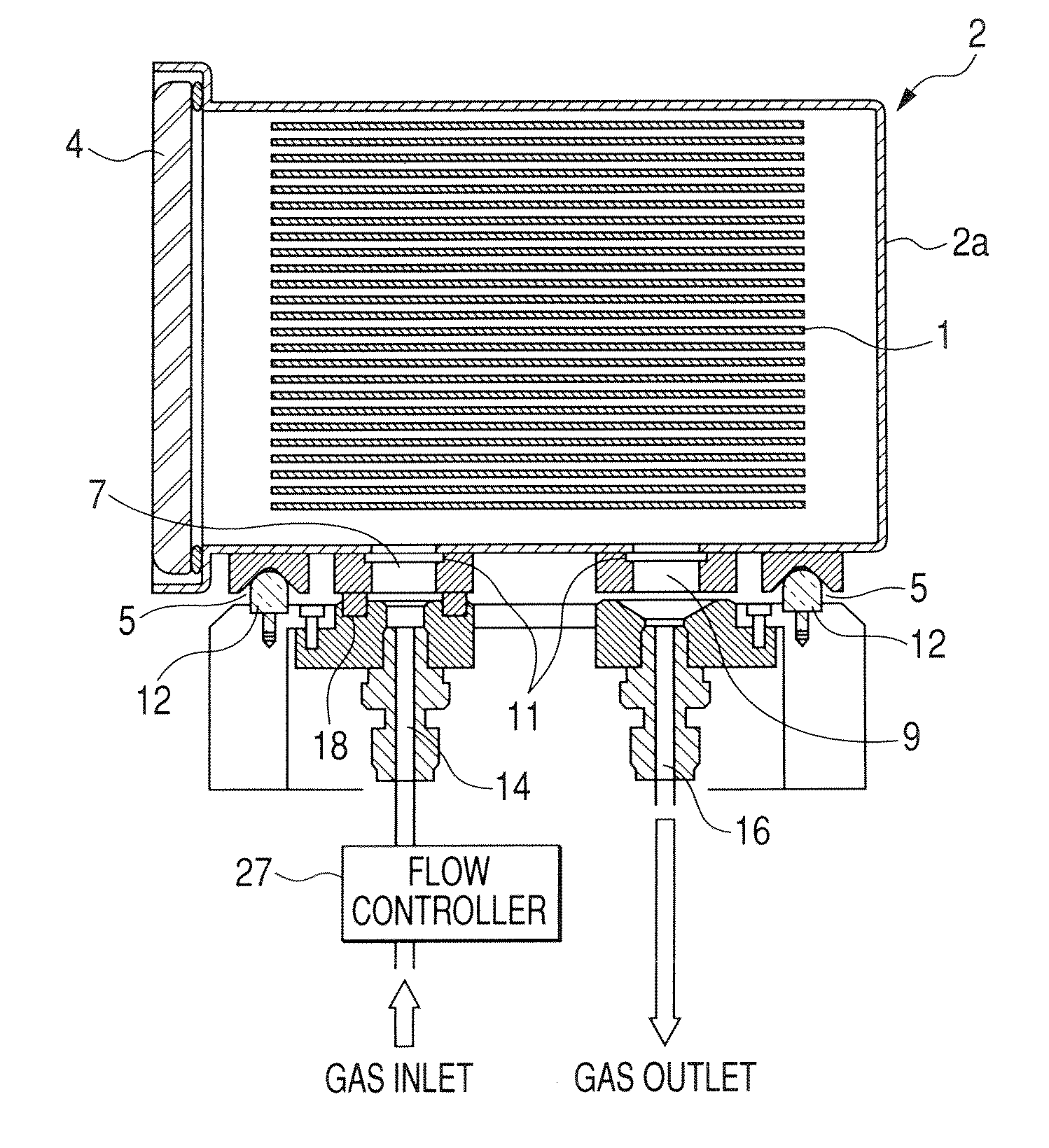
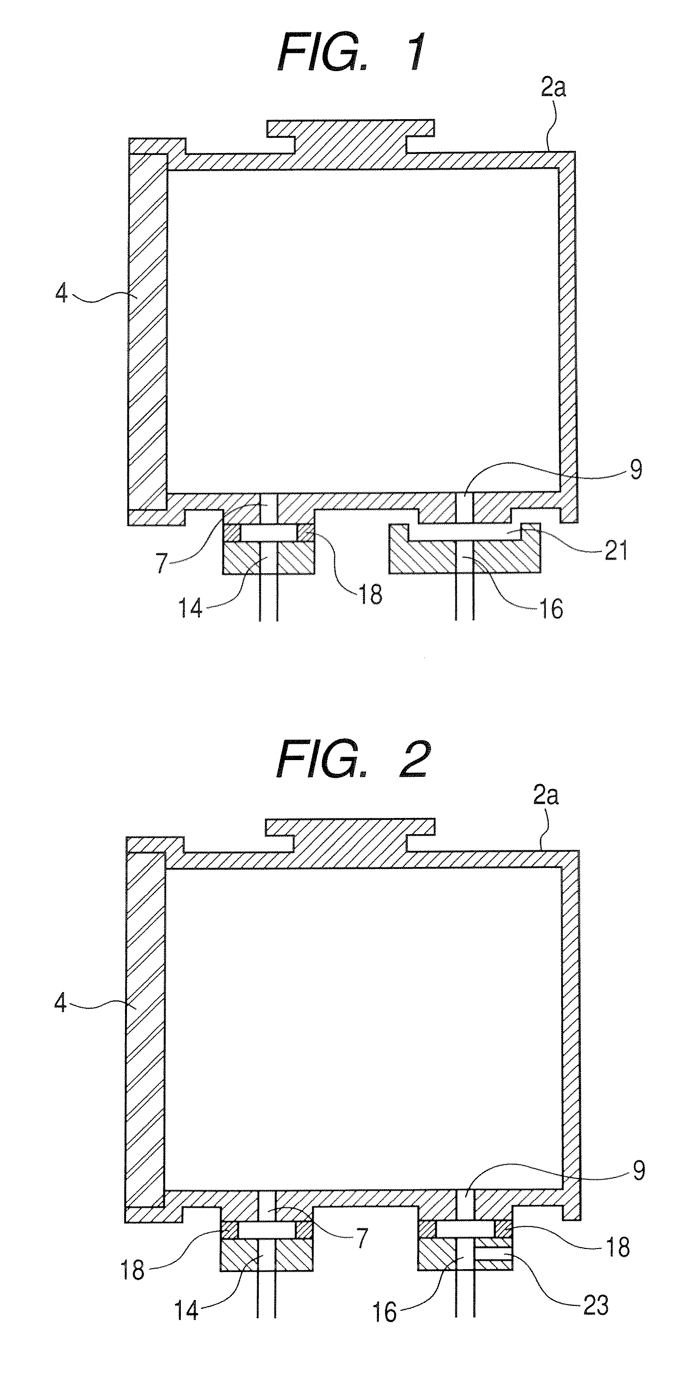
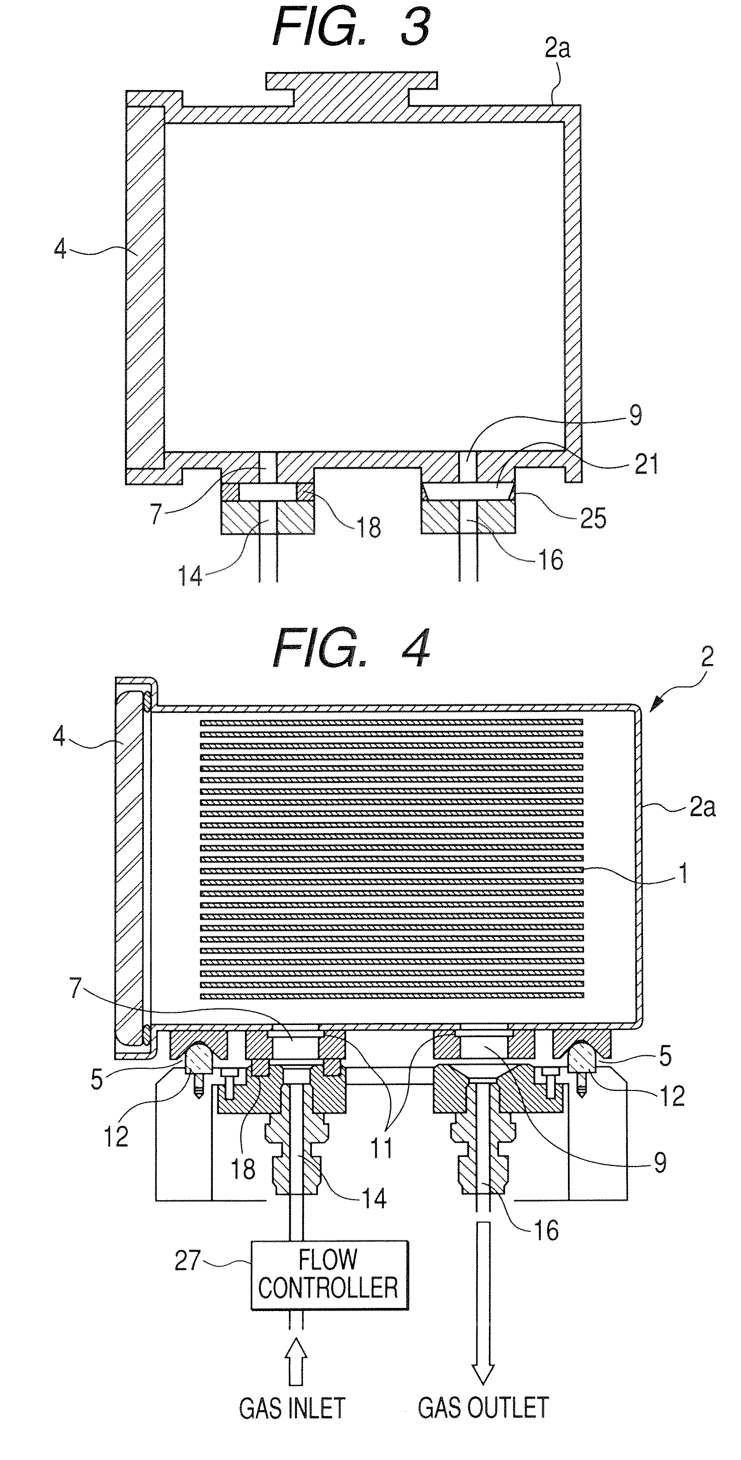
[0043] Now, a description will be given of embodiments of the present invention with reference to the accompanying drawings. FIG. 1 is a diagram schematically showing a purge system according to an embodiment of the present invention. To be more specific, FIG. 1 schematically shows a structure of a pod 2, and a table side inlet port 14 and a table side outlet port 16 which are disposed on a table 53 of FIG. 6, taken along a vertical section thereof. In the figure, the same structures as those of the respective structures shown in FIG. 5 as the conventional art are denoted by identical references for description.

[0044] Referring to FIG. 1, a sealing member 18 that is fixed to the table 53 side is interposed between an inlet port 7 of the pod 2 and a table side inlet port 14 that is connected to the inlet port 7. Therefore, a gas inlet system is completely sealed from an external space of the pod 2. On the contrary, no sealing member 18 is interposed between a outlet port 9 and a tab...


PUM


Abstract

For the purpose of preventing a pressure difference from occurring between an interior of an FOUP and an exterior at the time of purging the interior of the FOUP, a communication path that communicates with the exterior of the FOUP and the interior of an outlet path is provided with respect to the outlet path that extends from a table side outlet port which is disposed on a table on which the FOUP is placed, and an external atmosphere is introduced to the outlet path through the communication path when a pressure difference starts occurring between the interior and the exterior of the FOUP.

Description

BACKGROUND OF THE INVENTION [0001] 1. Field of the Invention [0002] The present invention relates to a product container employed for containing a product such as a semiconductor, a panel for a flat panel display, or an optical disk in a product manufacturing process conducted under a high clean envelopment, and a so-called load port for conducting an open / close operation of the container. In particular, the present invention relates to a purge system for replacing a gas sealed in a so-called front-opening unified pod (FOUP) where the product is used as an object to be contained in processing of wafer of the above product, mainly, a semiconductor wafer that is 300 mm in diameter, and a table used in structuring the purge system. [0003] 2. Related Background Art [0004] Up to now, in a process of manufacturing a semiconductor device, an overall factory in which a wafer is subjected to various processing is brought to a clean room state to cope with a demand for high cleaning during th...

Claims


Application Information

Patent Timeline
IPC IPC(8): B65B31/00
CPCH01L21/67393H01L21/67775H01L21/67763H01L21/02
Inventor OKABE, TSUTOMUSUZUKI, HITOSHI
Owner TDK CORPARATION
Why Eureka
Try Eureka