
Apparatus and method for switchable conditional execution in a VLIW processor

a conditional execution and processor technology, applied in the field of apparatus for conditional execution in a processor, can solve the problems of longer execution latency and achieve the effect of reducing hardware complexity and saving energy consumption

Active Publication Date: 2006-12-21
IND TECH RES INST
View PDF11 Cites 51 Cited by
  • Summary
  • Abstract
  • Description
  • Claims
  • Application Information

AI Technical Summary

Benefits of technology

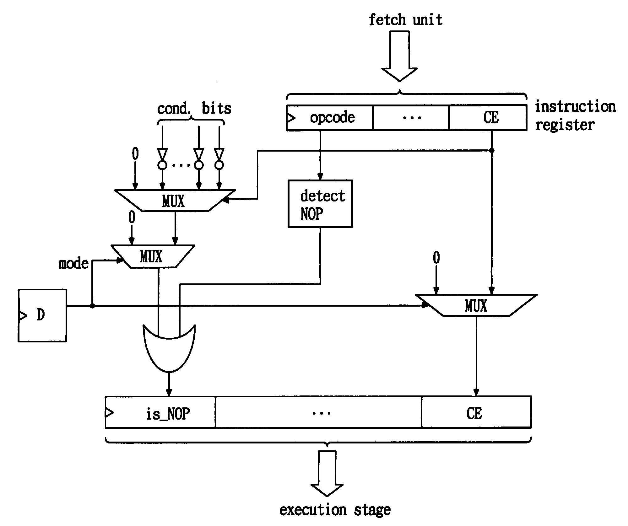
[0013] The present invention has been made to overcome the aforementioned drawback of conventional techniques. The primary object of the present invention is to provide an apparatus for conditional execution that can be used in a VLIW processor. The application of the present invention to the conventional VLIW processor can reduce the hardware complexity to realize conditional write-back. In addition, the present invention can switch between different execution modes. It can either perform the conditional execution in a conditional issue mode to save energy consumption or in a conditional write-back mode to achieve near-ASIC performance.
[0015] To achieve the aforementioned objects and features, the present invention provides a special instruction for switching between the energy-saving execution mode and the high-performance execution mode for conditional instructions. The execution of the special instruction will change the status register, which will affect the hardware operation of the processor. In the energy-saving mode, the processor will perform conditional execution using conditional issue mode described earlier. By determining the condition at an early stage of the pipeline, some instructions can be changed to NOP before execution. This saves energy. In the high-performance mode, the processor will perform conditional execution using conditional write-back mode. By delaying the determination of the condition to a later stage, the processor can schedule the instructions in a more parallel fashion to shorten the execution time.

Problems solved by technology

On the other hand, it has the disadvantage of longer execution latency.

Method used


Image

  • Apparatus and method for switchable conditional execution in a VLIW processor
  • Apparatus and method for switchable conditional execution in a VLIW processor
  • Apparatus and method for switchable conditional execution in a VLIW processor

Examples


Embodiment Construction

[0034]FIG. 7 shows a schematic view of a VLIW processor with an apparatus for switchable conditional execution according to the present invention. As shown in FIG. 7, the VLIW processor comprises a fetch unit 701, one or more instruction decoders 702, one or more ALU with control units 703, a register file 704, a plurality of source buses 705, a plurality of result buses 706, and a plurality of main buses 707. Wherein, the switchable conditional execution apparatus of the present invention comprises the one or more instruction decoders 702, the one or more ALU with control units 703, and the register file 704.

[0035] Without loss of generality, the embodiment in FIG. 7 is a six-issue VLIW processor, that is, the processor includes six decoders and six ALU with control units. The number of instruction decoders and ALU with control units can be varied according to the design. Fetch unit 701 in the VLIW processor fetches instructions and data from a memory (not shown), and load the ins...


PUM


Abstract

An apparatus for switchable conditional execution in a VLIW processor is provided, comprising one or more decoders, one or more ALU with control units, and a register file. The decoders loads and decodes said instructions from a fetch unit for decoding and sending the decoded instructions to the ALU with control units for execution. The register file stores and forwards the results on result buses to the decoders. The execution of a VLIW instruction includes a fetch stage, a decode stage, plural execution stages and a write-back stage. The invention has the features of approximate ASIC timing by conditional write-back with the compiler support for the conditional write-back, condition resolved just before write-back., software selective conditional issue and conditional write-back modes, and without hardware interlock / dependence checking for the VLIW processor.

Description

FIELD OF THE INVENTION [0001] The present invention generally relates to an apparatus for conditional execution in a processor, and more specifically to an apparatus and method for switchable conditional execution in a Very-Long Instruction Word (VLIW) processor for low energy-consumption and high performance. BACKGROUND OF THE INVENTION [0002] Many modern microprocessors use pipelining for performance purpose, for example, the Very-Long Instruction Word (VLIW) processors. Conditional execution has long been an important aspect of the pipeline execution. For those processors supporting conditional execution, their instruction set allows commands or selected commands marked as conditional mode. For example, the following statement assigns the value r4*r5 to the variable r3 only when r1 is greater than r2: if (r1>r2)r3=r4*r5; This statement may be complied into a conditional instruction supported by a hypothetical processor, as follows: cmpgt p0=r1, r2 [p0] mpy r3=r4*r5 where [p0...

Claims


Application Information

Patent Timeline
Patent Type & Authority Applications(United States)
IPC IPC(8): G06F9/44
CPCG06F9/30072G06F9/30181G06F9/3836G06F9/3857G06F9/3859G06F9/3885G06F9/3853G06F9/30189G06F9/38585G06F9/3858
Inventor MA, YUNG-CHENGWANG, TENGH-YIHKUO, HSIEN-FENG
Owner IND TECH RES INST
Learn More