Flux barrier type synchronous reluctance motor and rotor thereof

a synchronous reluctance motor and synchronous reluctance technology, which is applied in the direction of magnetic circuit rotating parts, magnetic circuit shape/form/construction, windings, etc., can solve the problems of increasing the weight of the rotor, increasing the entire production cost, prolonging the entire production time, etc., and reducing the fabrication cost and weight. , the effect of reducing the fabrication tim

Inactive Publication Date: 2006-12-21
LG ELECTRONICS INC
View PDF1 Cites 35 Cited by
  • Summary
  • Abstract
  • Description
  • Claims
  • Application Information

AI Technical Summary

Benefits of technology

[0009] Therefore, an object of the present invention is to provide a flux barrier type synchronous reluctance motor capable of facilitating a fabrication process with a shortened fabrication time and capable of reducing a fabrication cost and a weight thereof, and a rotor thereof.

Problems solved by technology

Accordingly, each device for performing each process is required, and it takes a lot of time to form the filling part 27, thereby prolonging the entire production time and increasing a production cost.
Furthermore, since the filling part is formed of a non-magnetic metal member, an entire production cost is increased and a weight of the rotor is increased.

Method used


Image

  • Flux barrier type synchronous reluctance motor and rotor thereof
  • Flux barrier type synchronous reluctance motor and rotor thereof
  • Flux barrier type synchronous reluctance motor and rotor thereof

Examples


Embodiment Construction

[0029] Reference will now be made in detail to the preferred embodiments of the present invention, examples of which are illustrated in the accompanying drawings.

[0030] Hereinafter, a flux barrier type synchronous reluctance motor and a rotor thereof according to one embodiment of the present invention will be explained with reference to the attached drawings.

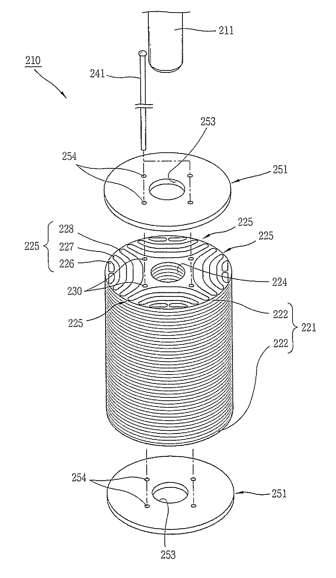
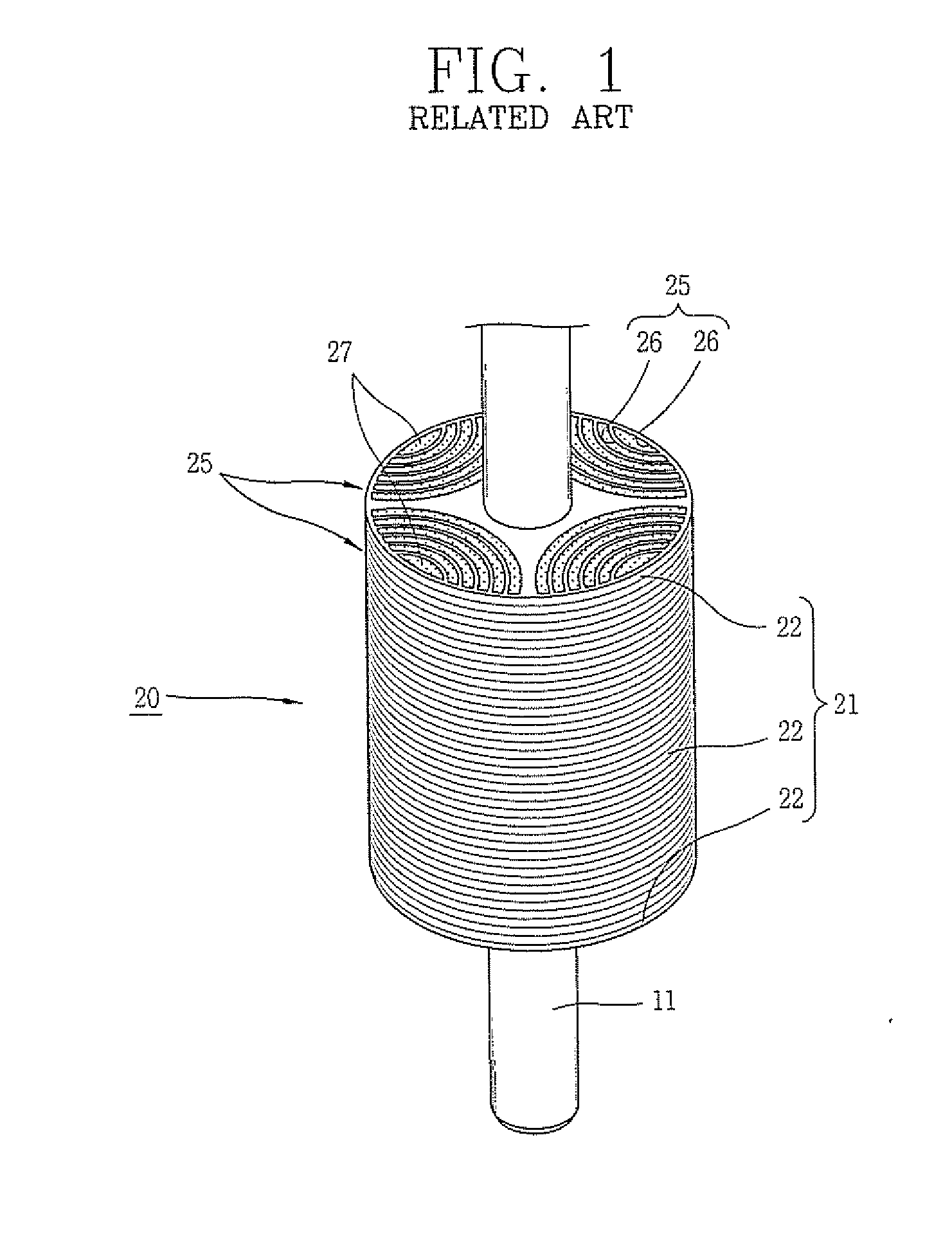
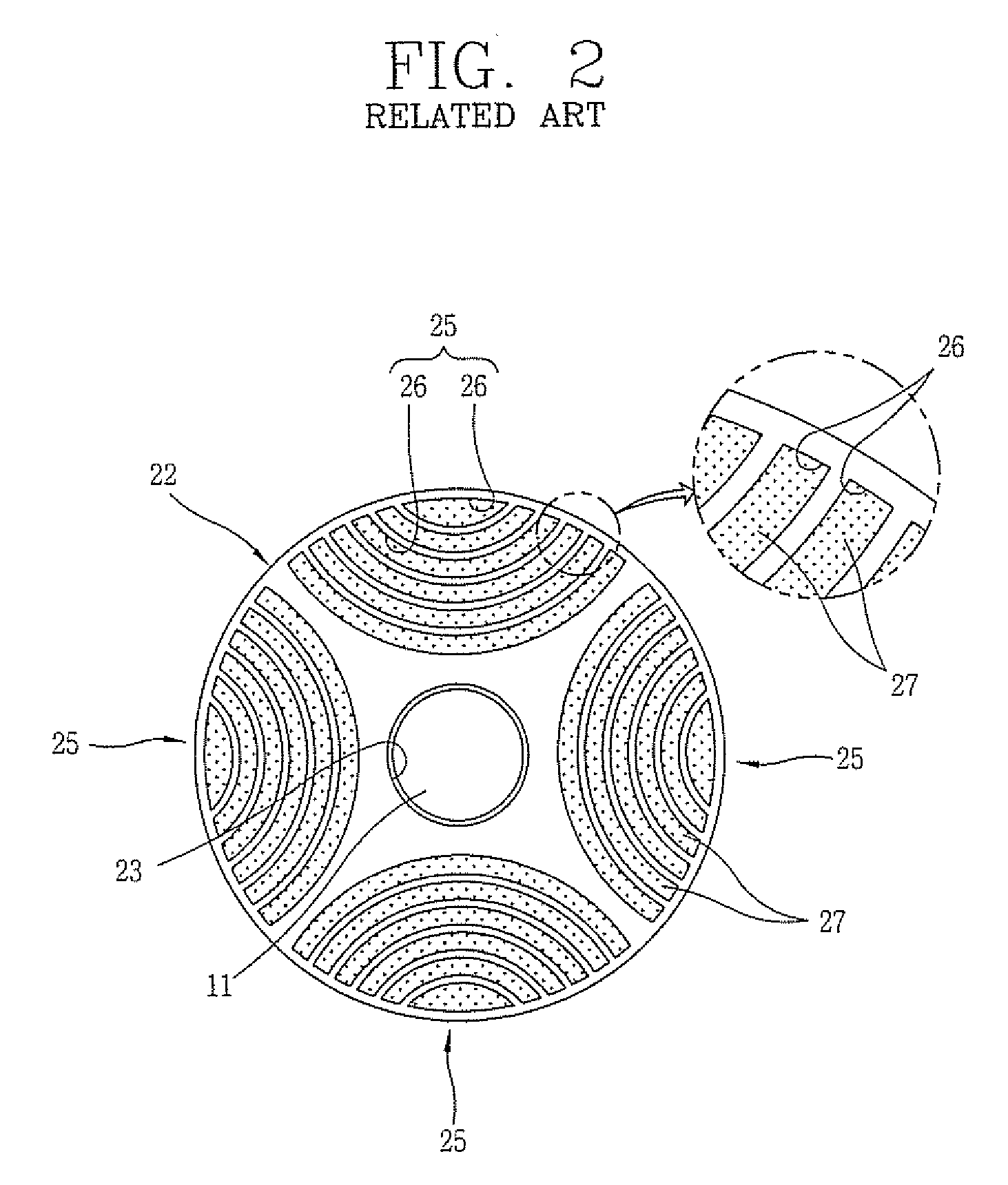
[0031] As shown in FIGS. 3 and 4, a flux barrier type synchronous reluctance motor according to the present invention comprises: a stator 110 including a stator core 111 having slots 115 and teeth 117 alternately formed along an inner diameter, and a stator coil 121 wound on the slot 115; and a rotor 210 including a rotation shaft 211, a rotor core 221, and a coupling member 241, wherein the rotor core 221 is formed by laminating a plurality of steel plates 222 to one another, the steel plate 222 having a shaft hole 224 for inserting the rotation shaft 211, a plurality of flux barrier groups 225 spaced from one another in a c...


PUM


Abstract

A rotor of a flux barrier type synchronous reluctance motor comprises: a rotation shaft; a rotor core formed as a plurality of steel plates are laminated to one another, the steel plate having a shaft hole for inserting the rotation shaft, a plurality of flux barrier groups spaced from one another in a circumferential direction and having a plurality of flux barriers spaced from one another in a radial direction, and a coupling hole penetratingly-formed between the adjacent two flux barrier groups; and a coupling member inserted into the coupling hole and fixing the steel plate. Accordingly, a fabrication cost and an entire weight of the motor are decreased, and a fabrication process is facilitated with a shortened fabrication time. Also, a large coupling intensity is obtained and a magnetic saturation does not occur, thereby preventing a function degradation of the motor.

Description

BACKGROUND OF THE INVENTION [0001] 1. Field of the Invention [0002] The present invention relates to a flux barrier type synchronous reluctance motor and a rotor thereof, and more particularly, to a flux barrier type synchronous reluctance motor capable of facilitating a fabrication process with a shortened fabrication time and capable of reducing a fabrication cost and an entire weight thereof, and a rotor thereof. [0003] 2. Description of the Background Art [0004] As shown in FIGS. 1 and 2, a rotor of the conventional flux barrier type synchronous reluctance motor comprises a rotation shaft 11, and a rotor core 20 rotatably arranged centering around the rotation shaft 11. [0005] The rotor core 20 comprises a core body 21 having a plurality of flux barriers 26, and a filling part 27 formed in each of the flux barriers 26. The core body 21 is formed by laminating a plurality of steel plates 22 having a disc shape to one another. The steel plate 22 is formed of a magnetic member, and...

Claims


Application Information

Patent Timeline
IPC IPC(8): H02K19/20H02K1/06H02K1/22
CPCH02K1/246H02K1/28H02K3/46H02K15/024
Inventor LEE, KYUNG-HOONWON, JUNE-HEECHEONG, DAL-HOAHN, JUN-HOOH, JAE-YOON
Owner LG ELECTRONICS INC
Why Eureka
Try Eureka