Eureka AIR delivers breakthrough ideas for toughest innovation challenges, trusted by R&D personnel around the world.

Gutter cover

Active Publication Date: 2006-12-21
PREMIER GUTTER COVER
View PDF49 Cites 25 Cited by
  • Summary
  • Abstract
  • Description
  • Claims
  • Application Information

AI Technical Summary

Benefits of technology

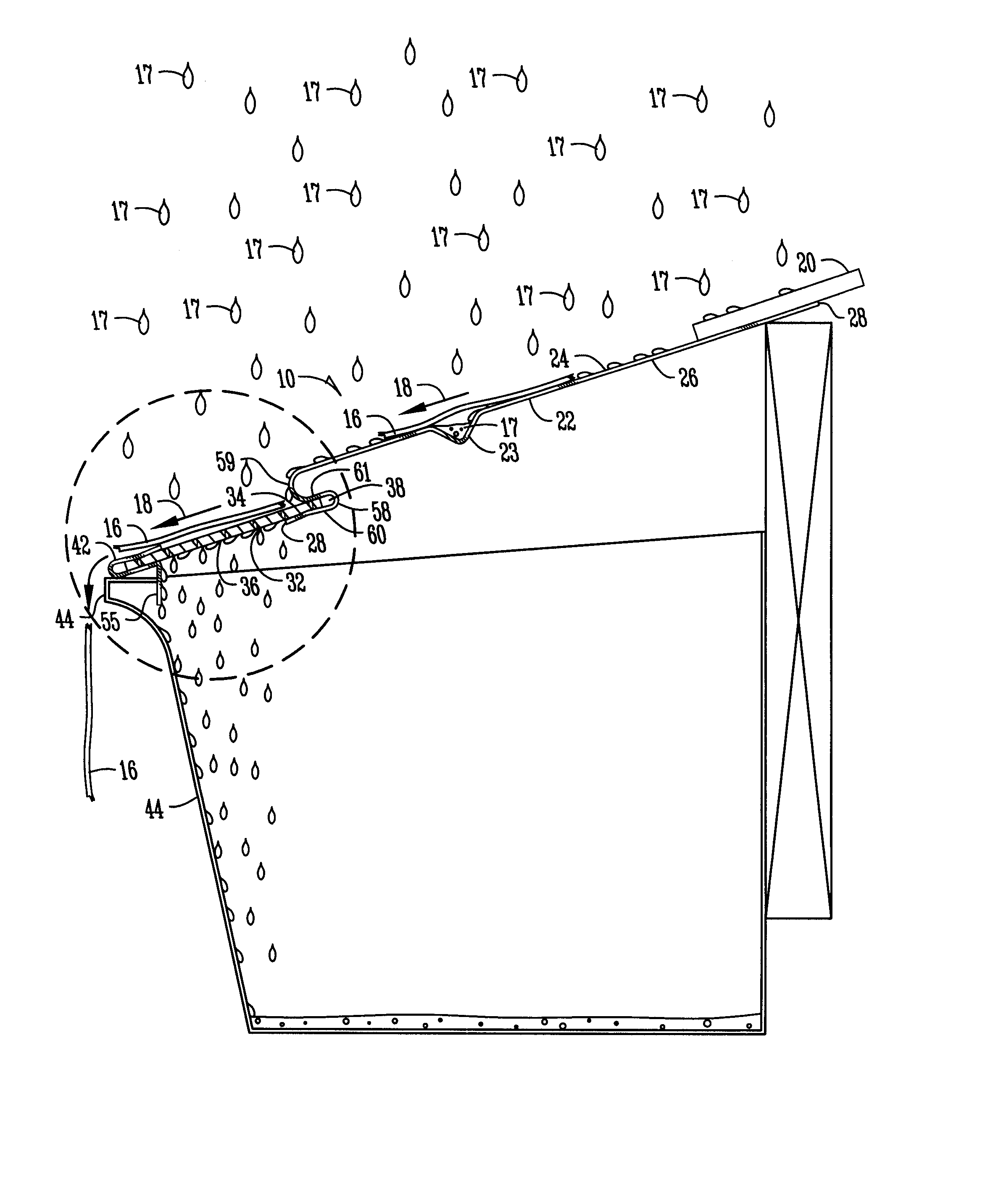
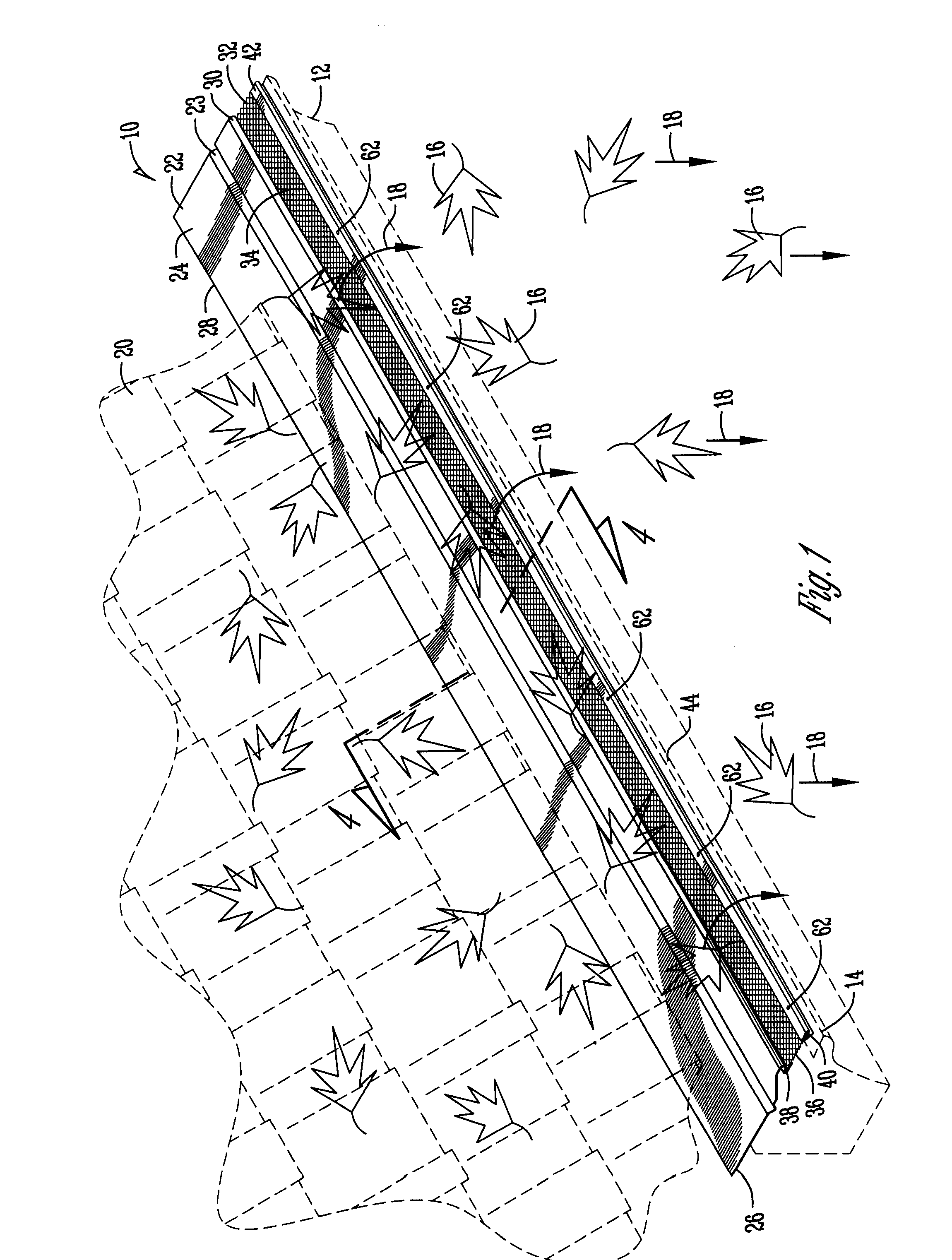
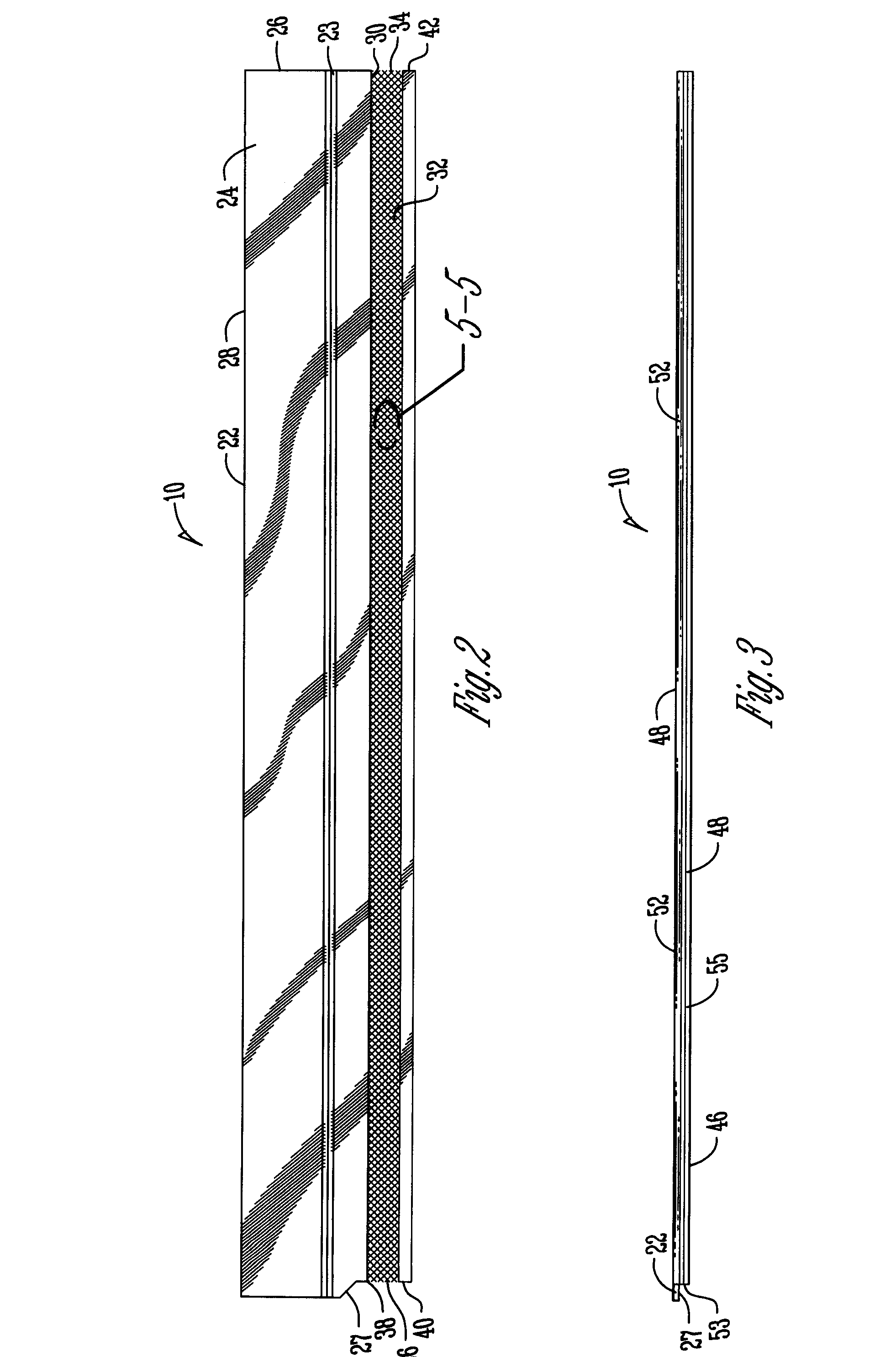
[0011] In its broadest sense, the invention comprises a gutter cover. The gutter cover distributing water across the face of the cover and controlling the rate of water ingress through the cover into the gutter thereby assisting in the separation of water and shedding of debris from the passing runoff water and debris, and preventing debris from building up on the gutter cover. The gutter cover includes a solid sheet member having a top surface, an opposite bottom surface, a first edge for positioning under a roofing material and a second parallel edge. The gutter cover also includes an expanded metal member having a top surface, an opposite bottom surface, a first and second parallel edges, where the first edge is secured to the second edge of the solid sheet member. A breaker plate is secured to the second edge of the expanded metal member to thereby assist in preventing water on the bottom surface of the expanded metal member from traveling beyond the second edge over the gutter. The expanded metal member further includes a plurality of honeycomb shapes each having parallel sides. The honeycombs shapes are connected by overlapping a pair of the sides. The longitudinal width between the overlapping sides is greater than the latitudinal width between the overlapping sides. A plurality of louvered surfaces are formed by the pair of overlapping sides. And, the louvered surfaces have an angle greater than 90 degrees with respect to the top surface of the expanded metal member. The angle of the louvered surfaces helps distribute water across the face of the expanded metal member and controls the rate of water ingress through the plurality of honeycombs into the gutter. The angles of the louvered surface also assists in the separation of water and shedding of the debris from the passing runoff water and debris, and prevents debris from building up on the gutter cover.
[0014] According to another feature of the present invention, the breaker plate further comprises parallel edges, a top and an opposite bottom surface, a first fold creating a first flap for crimping the expanded metal member to the breaker plate between the first flap and the bottom surface of the metal member. The breaker plate also includes a second parallel fold creating a second flap for preventing water on the bottom surface of the expanded metal member from traveling over the gutter.
[0017] According to another feature of the present invention, the first edge of the solid sheet member slides up under the roofing material to thereby assist in the transition of runoff water and debris from the roof onto the gutter cover.

Problems solved by technology

These embodiments often captured and stalled debris of all sizes on top of the mesh because of the high rate of water ingress through the screen.
However many of these embodiments because of the convexity of the screen also presented crevices and nooks where debris could collect and ultimately clog the screen.
These proved effective for the first few months after installation but eventually clogged due to the fineness of the mesh.
These often used a piece of sheet metal in combination with a medium mesh size expanded metal; however, after time the expanded metal still collected debris and exhibited an impaired shedding ability.
Previous attempts also failed to realize the importance of the angle of the louvered surfaces within various expanded metals and the direction of the louver with respect to the direction of the flow of the runoff water.

Method used


Image

  • Gutter cover
  • Gutter cover
  • Gutter cover

Examples


Embodiment Construction

[0025] Turning now to the drawings in which similar reference characters denote similar elements through the several views. Illustrated in FIGS. 1-6 is the combination of various views and in-use configurations of the gutter cover. The gutter cover being described with particularity herein.

[0026] The gutter cover is referred to generally as 10. In FIG. 1, the gutter cover 10 is shown positioned over the gutter 12. The gutter cover 10 is secured to the gutter 12 using zip screws 62. The zip screws 62 fasten through the breaker plate 42 into the front edge 14 of the gutter 12. The gutter plate 10 has a solid sheet member 22. The solid sheet member 22 has a top surface 24 and opposite bottom surface 26. The solid sheet member 22 also includes a first edge 28 and a second parallel edge 30. The first edge 28 of the solid sheet member 22 is positioned beneath the roofing material 20. Thus, the gutter cover 10 is secured firmly having the first edge 28 of the solid sheet member 22 positio...


PUM


Abstract

A gutter cover distributing water across the face of the cover and controlling the rate of water ingress through the cover into the gutter thereby assisting in the separation of water and shedding of debris from the passing runoff water and debris, and preventing debris from building up on the gutter cover.

Description

CROSS-REFERENCE TO RELATED APPLICATIONS [0001] This application is a continuation-in-part of U.S. patent application Ser. No. 29 / 232,460 filed on Aug. 4, 2005, which is a nonprovisional U.S. design application, herein incorporated by reference in its entirety.FIELD OF THE INVENTION [0002] The present invention relates generally to a gutter cover. The gutter cover distributes water across the face of the cover and controls the rate of water ingress through the cover into the gutter thereby assisting in the separation of water and shedding of debris from the passing runoff water and debris, and preventing debris from building up on the gutter cover. BACKGROUND OF THE INVENTION [0003] Numerous attempts have been made to construct a gutter cover capable of dealing with various and sundry types of debris, weather conditions and volume flows of runoff water from a roof. The first embodiments of the gutter cover were constructed under the school of thought that increasing the gap size of t...

Claims


Application Information

Patent Timeline
IPC IPC(8): E04D13/00
CPCY10T428/24306E04D13/076
Inventor GREGG, DAVID
Owner PREMIER GUTTER COVER
Why Eureka
Eureka Blog
Learn More