
Electromagnetic fuel injection valve

a fuel injection valve and electromagnet technology, applied in the direction of valve operating means/release devices, machines/engines, mechanical equipment, etc., can solve the problems of poor productivity and limited to the case where the fuel inlet tube is plastically deformed, and achieve high hardness and high productivity

Inactive Publication Date: 2006-12-07
KEIHIN CORP
View PDF7 Cites 6 Cited by
  • Summary
  • Abstract
  • Description
  • Claims
  • Application Information

AI Technical Summary

Benefits of technology

[0005] The present invention has been achieved under the above-mentioned circumstances, and it is an object thereof to provide an electromagnetic fuel injection valve with high productivity by enabling a retainer pipe to be fixed to a fuel inlet tube by crimping even when the fuel inlet tube is formed from a high hardness magnetic material.
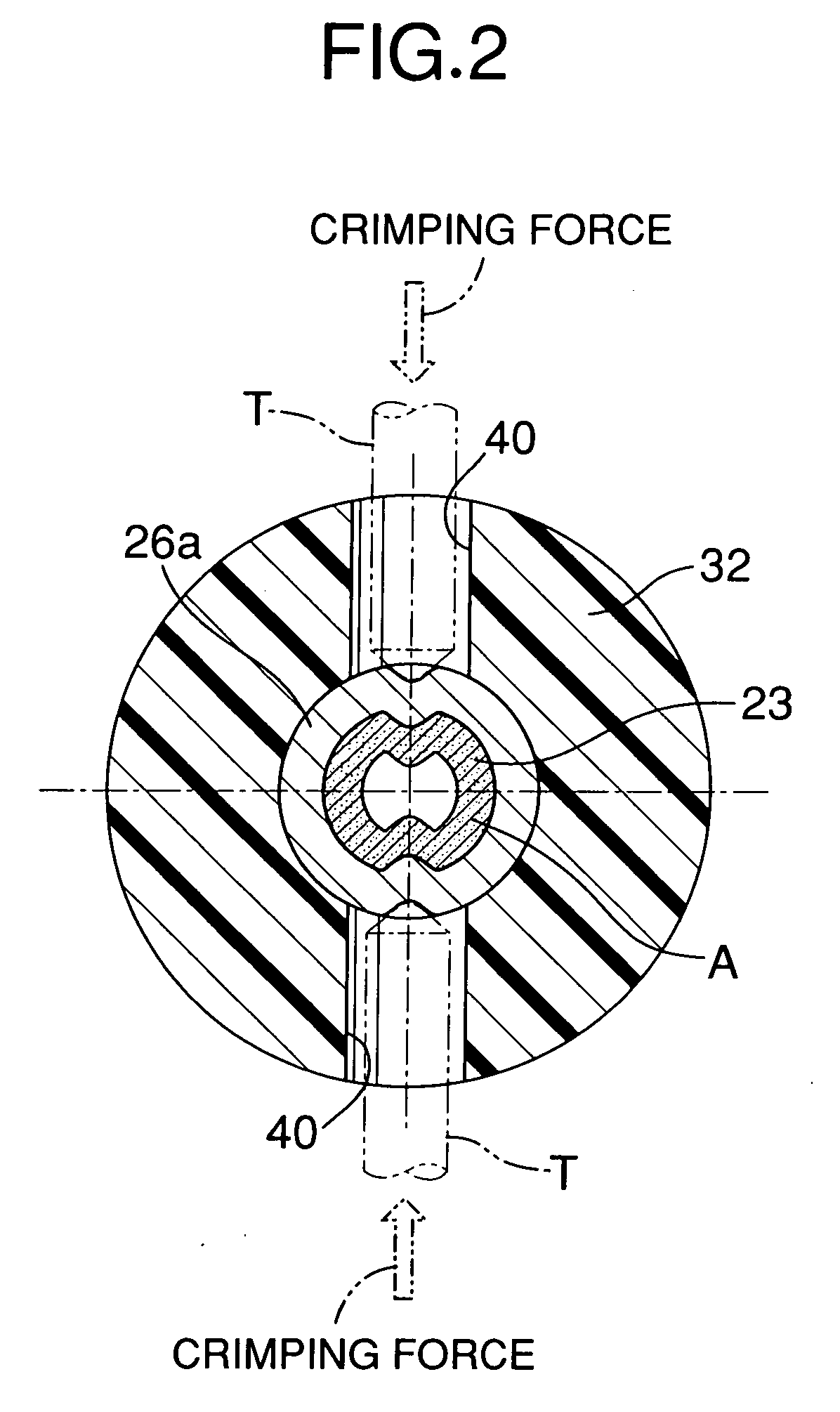
[0007] In accordance with this first aspect, even though the fuel inlet tube is made of the high hardness magnetic material, the softened region can be crimped. Therefore, making adjustment of the insertion depth easy by inserting the retainer pipe into the fuel inlet tube with a clearance fit enables the set load of the valve spring to be adjusted easily, and crimping the softened region subsequent to the adjustment enables the retainer pipe to be fixed to the fuel inlet tube, thereby improving the productivity.
[0009] In accordance with this second aspect, the softened region can have a degree of constriction of about 60% or higher, and fixing of the retainer pipe to the fuel inlet tube by crimping can be carried out easily and reliably.
[0011] In accordance with this third aspect, the magnetic path-forming member, which has good magnetic properties, a high HRC hardness of 20 to 40 without subjecting it to a surface hardening treatment, and excellent abrasion resistance, can be obtained together with the fuel inlet tube at low cost.

Problems solved by technology

However, the former means has poor productivity since it requires skill to finely adjust the depth to which the retainer pipe is press-fitted into the fuel inlet tube.
The productivity of the latter means is good since the insertion depth can be adjusted easily by inserting the retainer pipe into the fuel inlet tube with a clearance fit, and crimping of the fuel inlet tube after the adjustment of the set load of the valve spring is relatively easy, but it is limited to cases where the fuel inlet tube is capable of being plastically deformed.
Therefore, when the fuel inlet tube is molded from a high hardness magnetic material integrally with magnetic path-forming members such as a fixed core and a yoke, the latter means is unsuitable.

Method used


Image

  • Electromagnetic fuel injection valve
  • Electromagnetic fuel injection valve
  • Electromagnetic fuel injection valve

Examples


Embodiment Construction

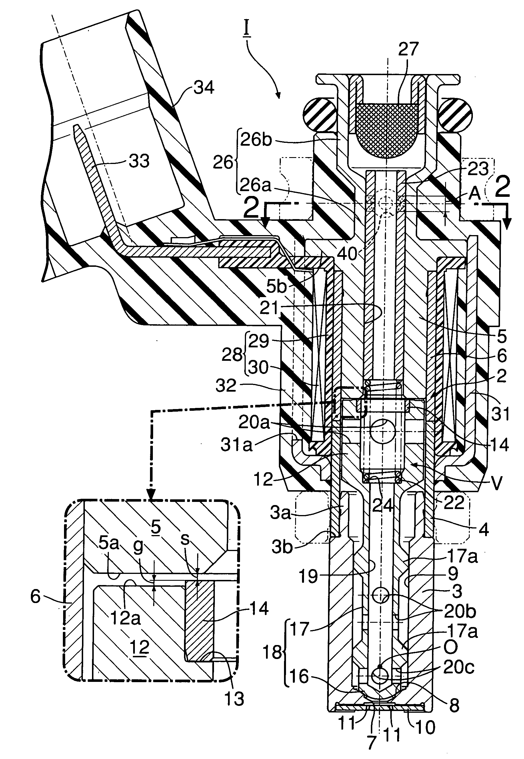
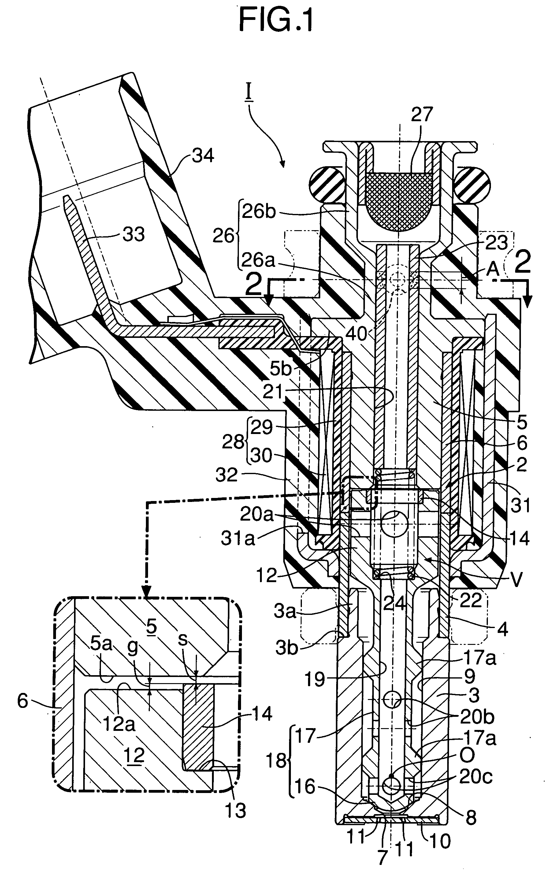
[0017] A preferred embodiment of the present invention is explained below with reference to the attached drawings.

[0018] In FIG. 1, a valve housing 2 of an electromagnetic fuel injection valve I for an internal combustion engine is formed from a cylindrical valve seat member 3 having a valve seat 8 at its front end, a magnetic cylinder 4 coaxially joined to a rear end section of the valve seat member 3, and a nonmagnetic cylinder 6 coaxially joined to the rear end of the magnetic cylinder 4.

[0019] The valve seat member 3 has on its rear end section a linking tubular portion 3a that projects, with an annular shoulder portion 3b, toward the magnetic cylinder 4 from an outer peripheral face of the valve seat member 3. By press-fitting this linking tubular portion 3a in the inner peripheral face of the front end portion of the magnetic cylinder 4 so as to make the front end face of the magnetic cylinder 4 abut against the annular shoulder portion 3b, the valve seat member 3 and the ma...


PUM


Abstract

An electromagnetic fuel injection valve is provided that includes a fuel inlet tube (26) extending from an outer end of a hollow fixed core (5), and a retainer pipe (23) that is inserted from the fuel inlet tube (26) into a hollow portion (21) of the fixed core (5) and supports a fixed end of a valve spring (22). The fuel inlet tube (26) is formed from a high hardness magnetic material, a retainer pipe 23-facing portion of the fuel inlet tube (26) is heated so as to form a softened region A, and this softened region A of the fuel inlet tube (26) is crimped toward the retainer pipe (23) so as to fix the retainer pipe (23) to the fuel inlet tube (26). In this way, even when the fuel inlet tube is formed from a high hardness magnetic material, the retainer pipe can be reliably fixed to the fuel inlet tube by crimping.

Description

FIELD OF THE INVENTION [0001] The present invention relates to an electromagnetic fuel injection valve used mainly in a fuel supply system of an internal combustion engine and, in particular, to an improvement of an electromagnetic fuel injection valve that includes a hollow fixed core, a fuel inlet tube extending from an outer end of the fixed core, a valve assembly having a movable core disposed so as to oppose the fixed core, a valve spring that is housed within a hollow portion of the fixed core and urges the valve assembly in a valve-closing direction, and a retainer pipe that is inserted from the fuel inlet tube into the hollow portion of the fixed core and supports a fixed end of the valve spring. BACKGROUND ART [0002] It is conventionally known that, in such an electromagnetic fuel injection valve, a set load of the valve spring is adjusted by changing the depth to which the retainer pipe is inserted into the fuel inlet tube. Furthermore, as means for fixing the retainer pip...

Claims


Application Information

Patent Timeline
IPC IPC(8): F16K31/02F02M51/06F02M61/16
CPCF02M51/0675F02M61/168F02M2200/9061
Inventor NAGAOKA, TAKAHIRO
Owner KEIHIN CORP
Learn More