Attachment device for a line

a technology of attachment device and line, which is applied in the direction of machine supports, transportation and packaging, and other domestic objects, can solve the problems of not providing satisfactory adaptation to different line diameters and adverse damping characteristics, and achieve the effect of minimizing the risk of injury

Inactive Publication Date: 2006-12-07
TRW AUTOMOTIVE ELECTRONICS & COMPONENTS GMBH & CO KG
View PDF6 Cites 34 Cited by
  • Summary
  • Abstract
  • Description
  • Claims
  • Application Information

AI Technical Summary

Benefits of technology

[0007] According to a second aspect of the invention, an attachment device for a line comprises a reinforcement part and a synthetic layer which at least partially surrounds the reinforcement part. The synthetic layer has a peripheral wall which surrounds the inserted line and has appendages extending inwards. The appendages have a sickle-like shape and are flexible. The appendages make it possible for lines with different line diameters to be inserted and held securely. Thus, with a line with a small diameter, the appendages are not bent, or are only slightly bent, and touch the outer side of the line with their tips, whereas with a larger line diameter, the appendages are bent (to a greater extent). In both cases, the line is securely and firmly encompassed.
[0008] According to a third aspect of the invention, an attachment device for a line comprises a reinforcement part and a synthetic layer. The reinforcement part has an attachment section. The synthetic layer fully surrounds the reinforcement part except for the attachment section. Any sharp edges of the reinforcement part which is made, e.g., from metal, are covered by the synthetic layer so that the risk of injury is minimized for a fitter. Furthermore, the lines, which are fully surrounded by the synthetic layer, are separated from the vibrations of the vehicle body, i.e. the synthetic layer surrounding the reinforcement part acts as a vibration damper.
[0010] The reinforcement part is preferably made from metal. Even in higher temperature ranges, metal is temperature-resistant so that there is no deterioration of the holding forces.
[0012] It is advantageous to provide the attachment device with a gap for inserting the line. The gap makes it possible to insert the line easily without the need for, e.g., a flap-type element which has to be opened and then closed again after the line has been inserted.

Problems solved by technology

To increase the holding forces, a more rigid material could be selected for the holding block; this, however, has an adverse effect on the damping characteristics thereof.
The walls of the line retainers are made to have simple ribs, which do not provide for satisfactory adaptation to different line diameters.

Method used


Image

  • Attachment device for a line
  • Attachment device for a line
  • Attachment device for a line

Examples


Embodiment Construction

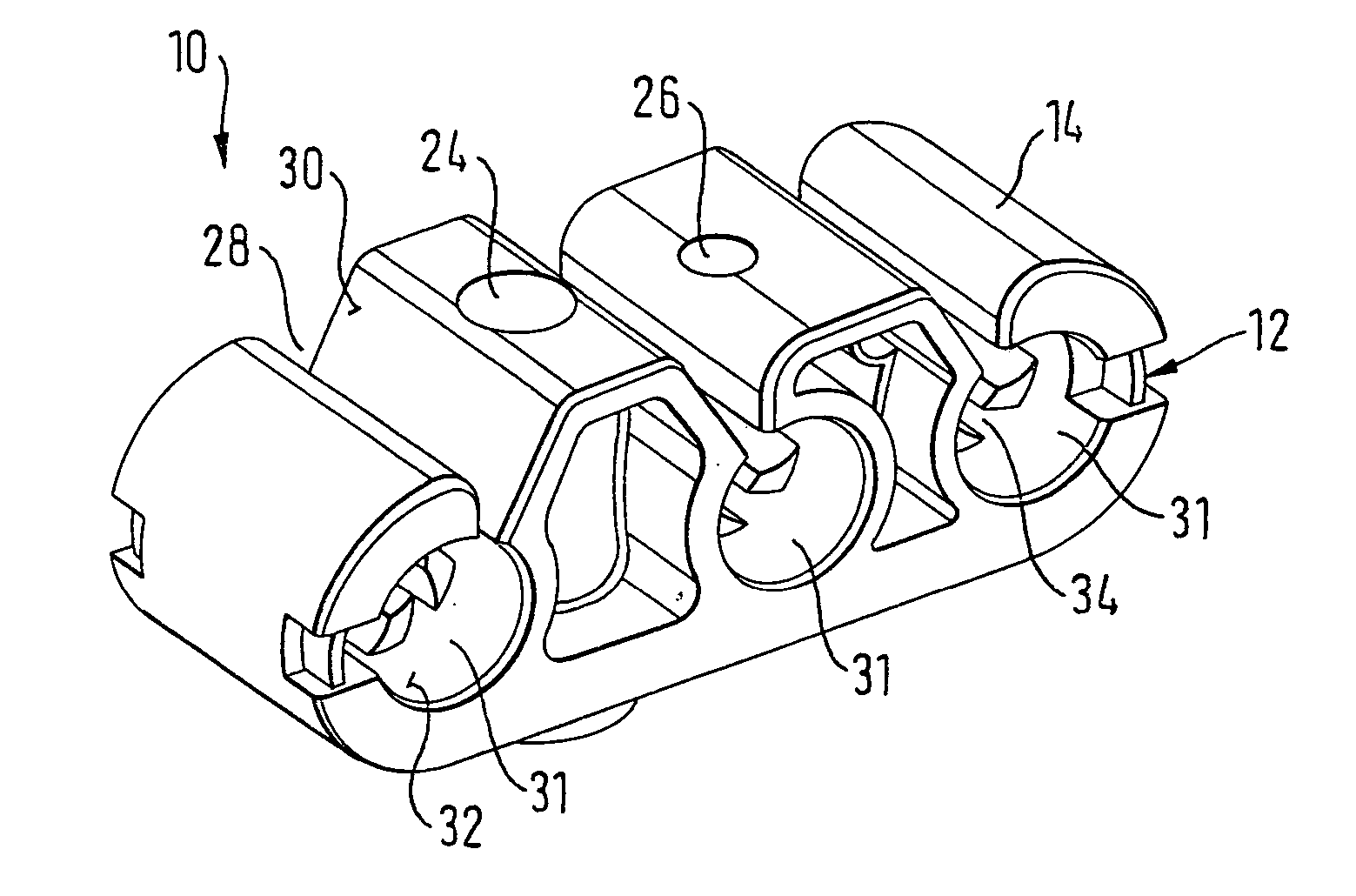
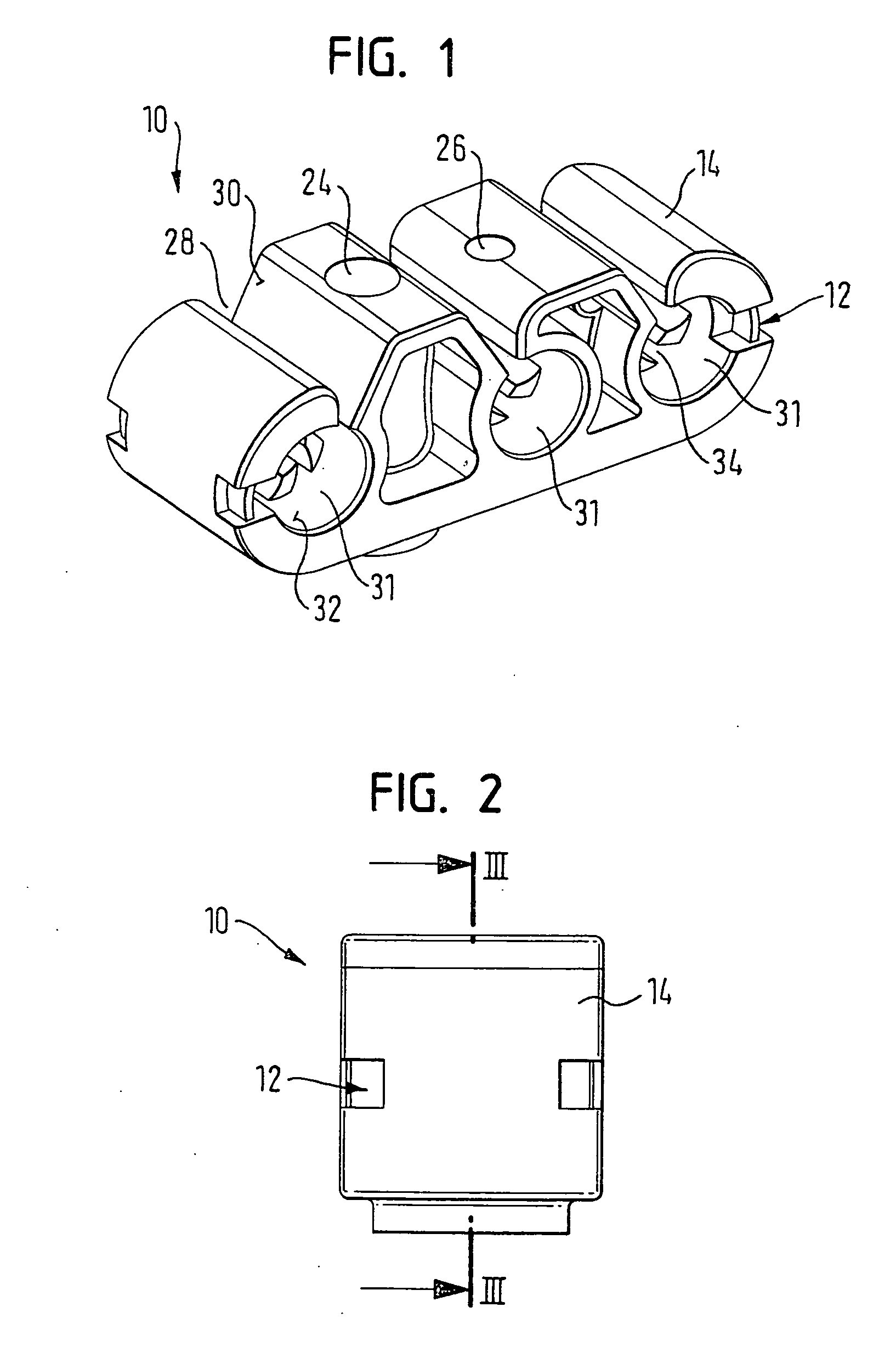
[0019]FIG. 1 shows an attachment device 10 which can accommodate three lines and which consists of a reinforcement part 12 (see FIG. 5) and a synthetic layer 14 which surrounds the reinforcement part 12.

[0020] The reinforcement part 12, which is embedded in the synthetic layer 14, is made from metal; however, it could also be made from a glass fiber reinforced polyamide, for example. At any rate, the material of the reinforcement part 12 is harder than the material of the synthetic layer 14.

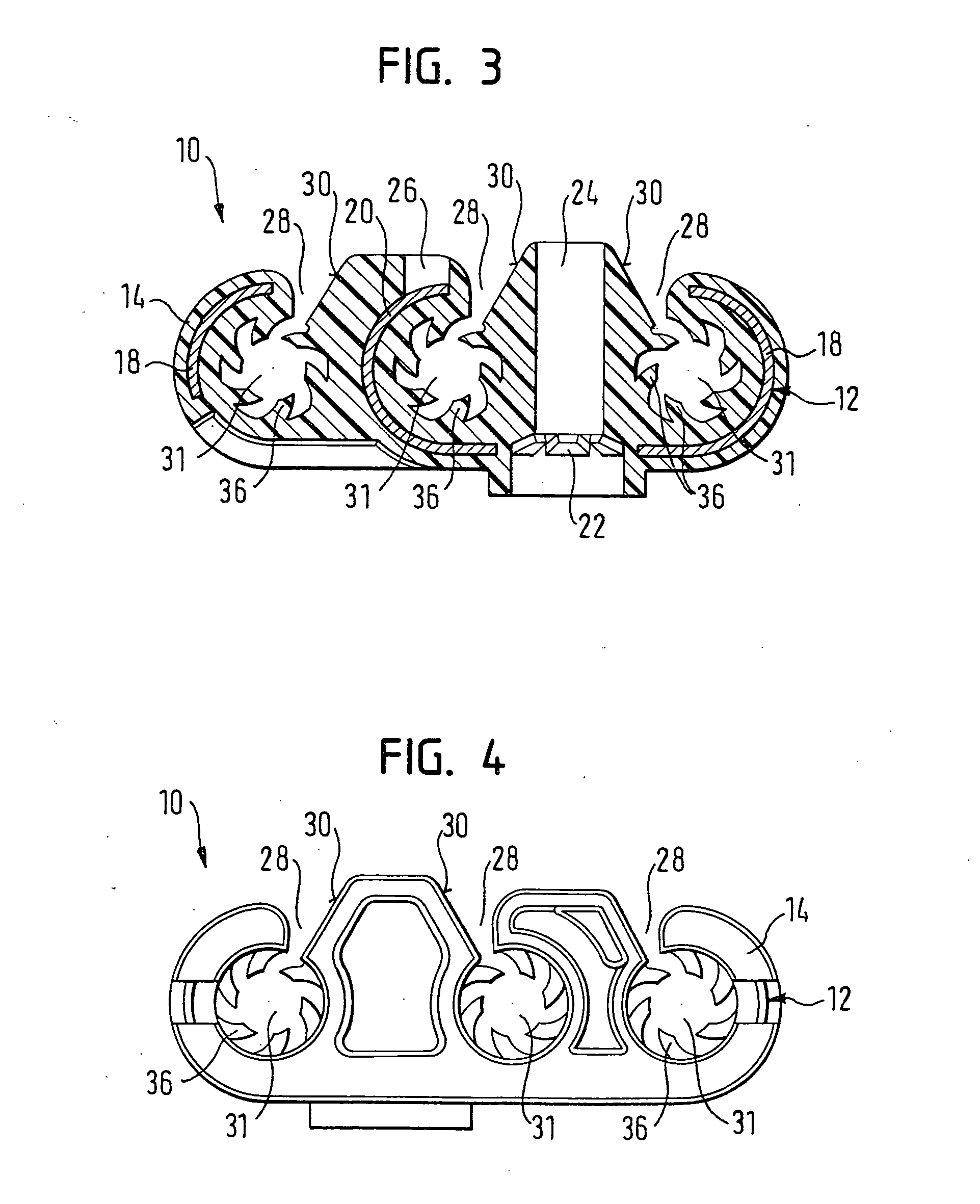
[0021] The reinforcement part 12 has a flat section 16 which on both sides continues into C-shaped sections 18, the flat section 16 also having a C-shaped section 20, as seen in cross-section, which is formed by a central strip of the flat section 16 being stamped out and bent upwards. Because of this, the width of the central C-shaped section 20 is less than that of the two outer C-shaped sections 18.

[0022] The flat section 16 also has an attachment section 22 which is in the form of a spring...


PUM


Abstract

An attachment device (10) for one or a plurality of lines includes a reinforcement part (12) and a synthetic layer (14) which at least partially surrounds the reinforcement part (12). A respective retainer is provided for each line. The reinforcement part (12) has a C-shaped section (18, 20), as seen in cross-section, for each retainer. Each C-shaped section (18, 20) surrounds the respective line spaced apart from the line. The synthetic layer (14) has a peripheral wall (32) which surrounds the inserted line and has appendages (36) extending inwards. The appendages (36) have a sickle-like shape and are flexible. The reinforcement part (12) has an attachment section (22) for a bolt. The synthetic layer (14) fully surrounds the reinforcement part (12) except for the attachment section (22). The synthetic layer (14) has a cylindrical opening (24) formed therein for accommodating the bolt.

Description

TECHNICAL FIELD [0001] The invention relates to an attachment device for one or more lines. BACKGROUND OF THE INVENTION [0002] Different attachment devices are known for the attachment of lines, such as hydraulic lines and electric wires in vehicles, especially for attachment to a vehicle body. There are different requirements on such devices. On the one hand, they are required to provide sufficient holding forces for lines, even in higher temperature ranges. On the other hand, it should be possible to produce them inexpensively, and they must not have any sharp edges so as to minimize the risk of injury for a fitter. [0003] DE-U-89 00 984 discloses an attachment device having an elastically bendable holding block. The holding block is divided into two separate block halves, which are spaced apart from each other. The block halves are held together by an embedded stabilizing body which is fully exposed in a certain region. Despite the stabilizing body, the forces for holding the lin...

Claims


Application Information

Patent Timeline
Patent Type & Authority Applications(United States)
IPC IPC(8): F16L3/22F16L3/02H02G3/32
CPCF16L3/223B60R16/0215H02G3/32F16L55/035
Inventor JATZKE, STEFAN
Owner TRW AUTOMOTIVE ELECTRONICS & COMPONENTS GMBH & CO KG
Why Eureka
Try Eureka