
Concrete truss

a technology of concrete trusses and beams, which is applied in the direction of bridges, building components, structural elements, etc., can solve the problems of increasing the cost and time of production, requiring significantly more steel and concrete, and no concrete truss is considered. to achieve the effect of conserving the position of design steel

Inactive Publication Date: 2006-12-07
MENTADO DURAN JAVIER
View PDF12 Cites 29 Cited by
  • Summary
  • Abstract
  • Description
  • Claims
  • Application Information

AI Technical Summary

Benefits of technology

[0010] Second.—to develop a Concrete Truss with more load capacity and slighter than the current prefabricated beams of concrete, to achieve more structural security.
[0031] Some separators can be placed during the casting of the concrete that guarantee the design cover, which will be able to retire when the consistency of the concrete is enough to conserve the position of the design steel.

Problems solved by technology

However, none considers the Concrete Truss, which has a better structural behavior due to the disposition of each one of their elements.
If the presently available reinforced concrete beams manufactured of constant section, were compared with the Concrete Truss under the same loads, the result would be that the presently available beams would require significantly more steel and concrete volume and also increase the cost and time of production.
The disadvantages of these materials are that they are not resistant to fire, have a very high cost of maintenance, and are less durable, in comparison with the Concrete Truss.

Method used


Image

  • Concrete truss
  • Concrete truss
  • Concrete truss

Examples


Embodiment Construction

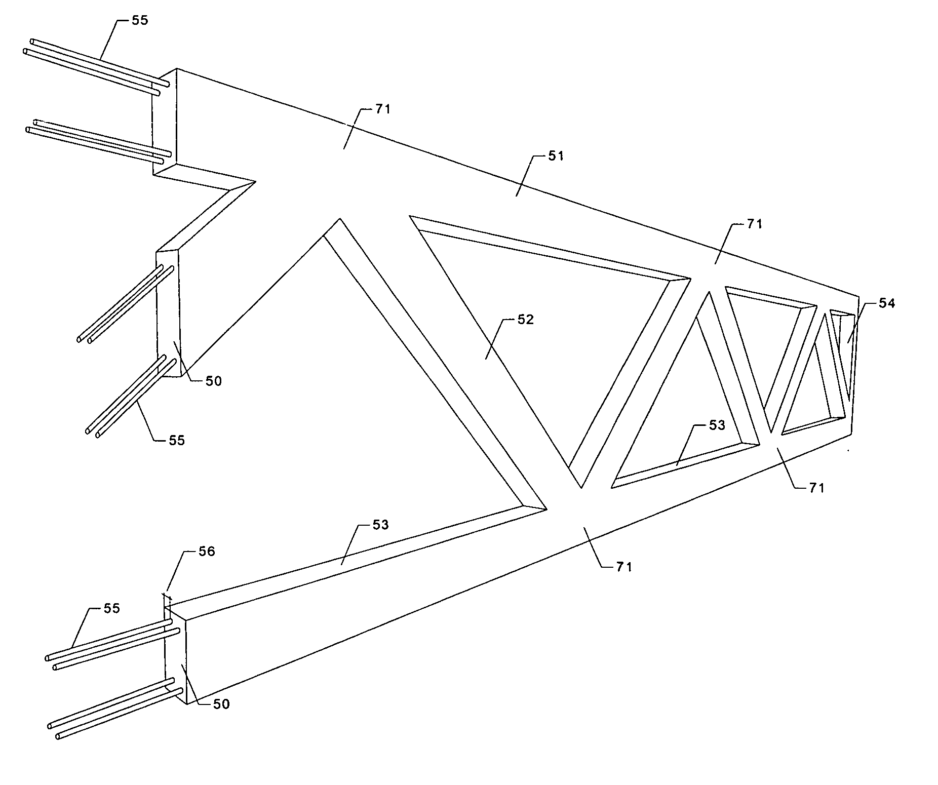
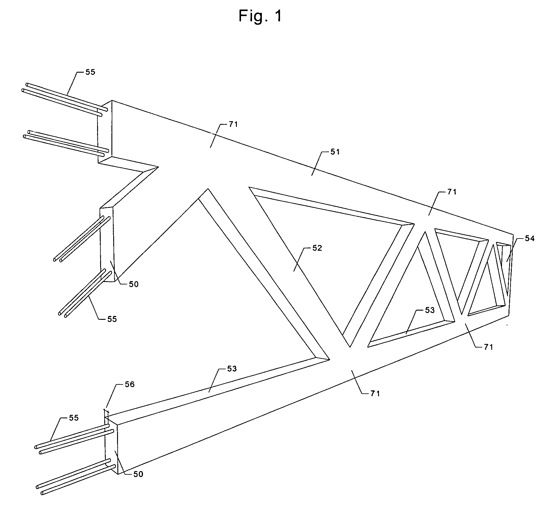
[0073]FIG. 1 depicts the perferred embodiment of the present invention denominated Concrete Truss in which the right pieces are observed (top chord 51, diagonals webs 52, bottom chord 53, vertical web 54), manufactured of concrete 50, reinforced steel 55, and the corresponding cover 56, according to the applicable norms. The present invention contemplates that reinforced steel 55 can also be pretressed or post-tensioned. The pieces are joined together monolithically 71, so that the external loads applied where they are joined produce stress directly on these pieces. The preferred embodiment contemplates that the basic geometric form of a triangle is used in the disposition of the elements, since it is the only geometric figure that is not deformed.

[0074] The elements that are shown in FIG. 1 have a disposition type Warren, they have a rectangular section as shown in FIG. 22, the steel reinforce concrete as shown in FIG. 19, and the union is monolithic as shown in FIG. 15. Important...


PUM


Abstract

A concrete structural framework comprised of a combination of reinforced steel, including pre-stressed and post-tensioned, with high performance concrete (HPC), for use in construction and other industries. This framework provides a highly fire resistant structure that is also resistant to the forces of nature and maintains a high level of structural integrity. The members of this concrete truss are joined or otherwise secured together by monolithic means, welded with badges, rivets, screws, or the like, in a triangular weblike configuration which provides the ultimate support against forces of compression and tension.

Description

RELATED DOCUMENTS [0001] The present application is related to the content of Document Disclosure No. 525632, filed Feb. 7, 2003. [0002] This is a non-provisional application relating to the content of, and claiming priority to, U.S. Provisional Patent Application Ser. No. 60 / 648,847, filed Jan. 31, 2005, which is incorporated by reference herein.FIELD OF INVENTION [0003] The present invention relates generally to the field of manufacture and use of Concrete Truss that have a longer time period of fire resistance and thus a high structural integrity. The present invention is also related to methods and the apparatuses for their manufacture within the field of construction, architecture, engineering and the precast and prestressed and post-tensioning industry. The examples presented are shown for purposes of illustration and not limitation. BACKGROUND OF THE INVENTION [0004] At the present time there are beams (joist) of reinforced concrete, (made in work, prefabricated, prestressed ...

Claims


Application Information

Patent Timeline
Patent Type & Authority Applications(United States)
IPC IPC(8): E04C3/02
CPCE01D2/00E01D6/00E01D2101/28E04B1/22E04B5/04E04C3/44E04B5/046E04C3/205E04C3/26E04C3/34E04B5/043
Inventor MENTADO-DURAN, JAVIER
Owner MENTADO DURAN JAVIER
Learn More