Golf spike

a golf spike and spike technology, applied in the field of golf spikes, can solve the problems of rigidity of the conventional tees, the inability to precisely set the ball elevation, and the inability to ensure the consistent distance from the ground, so as to increase the surface for advertising and more stability of the ball

Inactive Publication Date: 2006-11-23
CALDERON LUIS JR
View PDF14 Cites 13 Cited by
  • Summary
  • Abstract
  • Description
  • Claims
  • Application Information

AI Technical Summary

Benefits of technology

[0008] The top structure of this tee has a flexible top portion which can be manufactured from rubber, silicone, neoprene, plastic, flex foam or any other flexible, durable material. The ball sits on top of the flexible top structure. This new designed “ball seat” increases ball placement and stability and gives way to the impact of the golf club thereby reducing the force from the golfer's swing which allows the ball to reach its fullest potential. The top structure can be manufactured with a large seat for the ball which lessens the obstruction to the golfers swing and increases the stability of the ball. This top structure can be made in various shapes, geometry, textures and styles which does not change its utility. A few examples of the shapes are a cup design, barrel design, hour glass design, flute design, flower bulb / pedals design, tulip design, champagne glass design, soda / beer can design, or other geometrical designs. This top portion is open at the distal end and can either contain a thicker lipped rim, cupped or tapered rim or a rim which is a consistent diameter with the body of the top structure.
[0009] The top structure is flexible thus allowing for slight distortions in the golfers swing, the weather or terrain and still holding the ball in place. The flexible top structure offers the golfer's swing less impact due to the flexible outer walls of the cavity which offer reduced resistance and less energy loss at the point of impact. These facts enable the golfer to drive the ball farther. The rubber flexes and therefore is more difficult to break or tear thereby making these tees far more durable than the average tee. The flexible top structure is made with a material which has memory so that it rebounds to it's original shape when struck. Also, the rubber / flexible top structure is made in different heights to enable the golfer to consistently tee the ball at the same height every time depending on the type of shot desired. The walls of the top structure can be made of solid or perforated rubber like flexible material to allow air flow. The top structure can be stamped / printed to accommodate various logos and sponsor advertisement.
[0011] In a presently preferred embodiment, it is the object of this invention to provide a golf tee which can be set into the ground at a predetermined height, has a flexible top section allowing for more stability of the ball, a give when impact with the ball is made and an increased surface for advertising.

Problems solved by technology

These tees are designed to hold the ball off the ground however; the elevation of the ball can never be precisely set.
The higher or lower placement of the ball is normally achieved by how far the tee is pushed into the ground, however this method never insures the consistent distance from the ground.
Further, the rigidity of the conventional tees has many drawbacks, such as the ball potentially rolling off and not being securely held in place and lack of play when the ball is impacted with the club.
With traditional tees an “off swing” can strike the tee, thus breaking the swing, golfers concentration, breaking the tee and ruining the shot.
The conventional tees cannot be manufactured to always hold the ball at the same height off the ground.
Conventional tees cannot be manufactured at various heights to ensure that the golf ball will sit at a determined distance from the ground consistent with the users desire.
Conventional tees have a very small seat for the ball and newer plastic tees may break or shatter but because of their rigidity often hinder the golfer's swing.
Further, conventional wooden tees often break or shatter when hit by the user's golf club.
These conventional golf tees cause inconvenience to the user, and thereby limit the versatility of their use.

Method used


Image

  • Golf spike
  • Golf spike
  • Golf spike

Examples


Embodiment Construction

[0019] After reading this description it will become apparent to one skilled in the art how to implement the invention in various alternative embodiments and alternative applications. However, although various embodiments of the present invention will be described herein, it is understood that these embodiments are presented by way of example only, and not limitation. As such, this detailed description of various alternative embodiments should not be construed to limit the scope or breadth of the present invention as set forth in the appended claims.

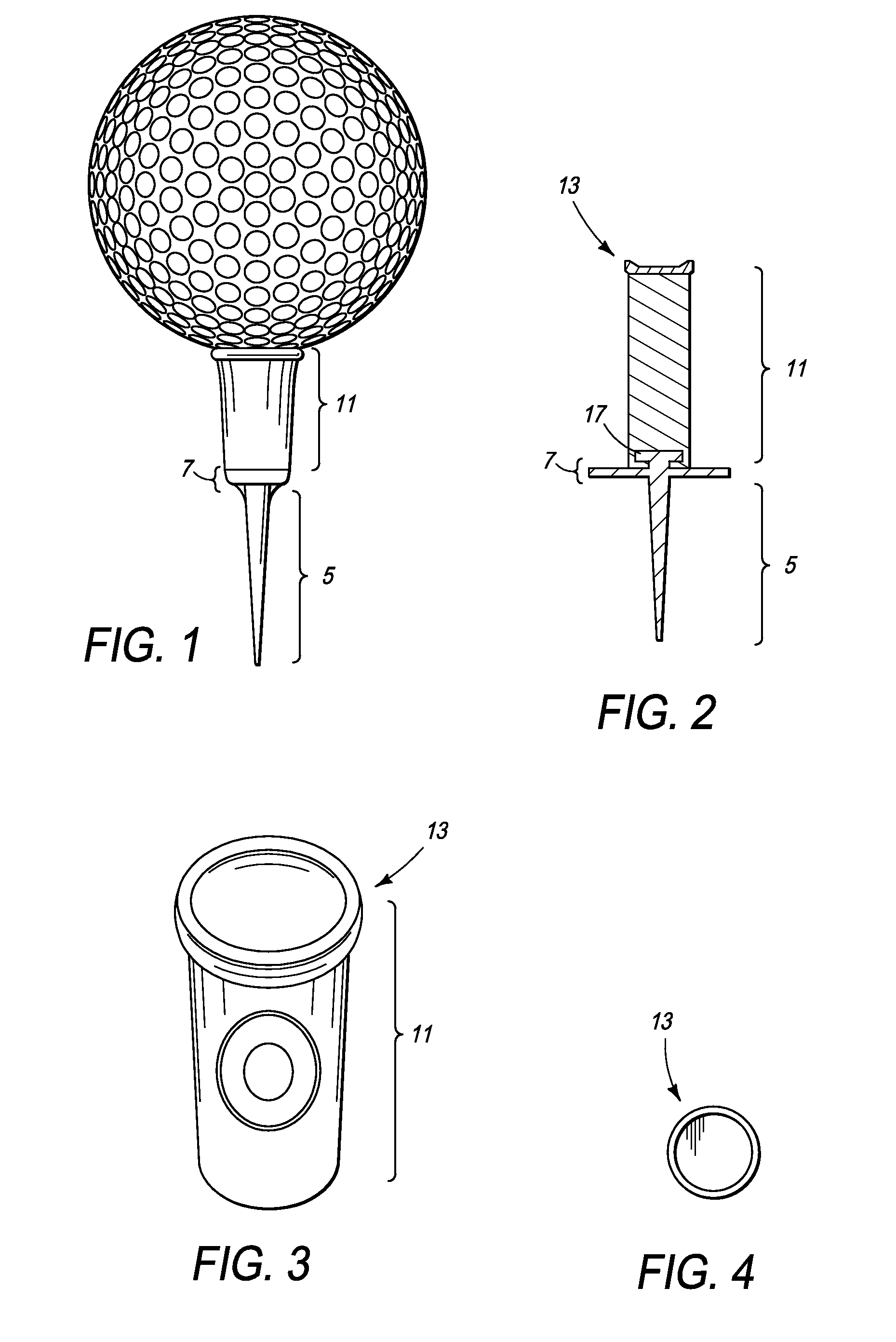
[0020] The present invention discloses a golf tee which securely holds golf balls and secondarily allow ample space for advertising media. This tee is designed with flexible top structure which in one embodiment can be formed from rubber, silicone, plastic, neoprene, foam, or any other composite pliable or flexible materials. The flexible top structure is made with a material which has memory so that it rebounds to it's original shape w...


PUM


Abstract

The present invention involves a golf tee used in the game of golf. The golf spike offers a variety of benefits to a golfer's swing and the game. The flexible top structure offers the golfer's swing less impact due to the flexible outer walls of the cavity which offer reduced resistance and less energy loss at the point of impact. Thus, allowing the ball to be driven further. These tees are more durable than the average tee. This present invention can be constructed from single or multiple component parts. The preferred embodiment includes a tapered rigid shaft connected to a flexible cup-shaped structure with a rim which holds the golf ball. The flexible top structure benefits the golfer by allowing for slight distortions and still holds the ball in place. The flexible cup like structure can further act as a space to house advertising media. The golf spike can be manufactured from a variety of materials such as, but not limited to, plastic, metal, wood, hard and pliable composites, foam or from any other material that will benefit the design concept and intent.

Description

BACKGROUND [0001] 1. Field of the Invention [0002] This invention relates generally to golf tees, and more particularly a tee which has a flexible top structure to place the ball a particular distance from the turf, to securely hold the ball, to allow play when the ball is struck by the club and to allow for a larger medium for advertising to be displayed. [0003] 2. Related Art [0004] Conventional golf tees with the exception of the “Brush Tee” are rigid in composition and do not contain a flexible top portion on which the ball rests. These tees are designed to hold the ball off the ground however; the elevation of the ball can never be precisely set. In some instances it is preferable to have the ball lower or higher off the ground depending on the terrain or the skill or physical attributes of the user. The higher or lower placement of the ball is normally achieved by how far the tee is pushed into the ground, however this method never insures the consistent distance from the grou...

Claims


Application Information

Patent Timeline
IPC IPC(8): A63B57/00
CPCA63B2057/0025A63B57/0018A63B57/15A63B57/10A63B57/13
Inventor CALDERON, LUIS JR.
Owner CALDERON LUIS JR
Why Eureka
Try Eureka