Information processing apparatus and method
a technology of information processing and information processing buffer, which is applied in the direction of electronic editing digitised analogue information signals, instruments, television systems, etc., can solve the problems of inability to efficiently decode pictures, inability to access pictures, and longer access time, so as to reduce the size of the decoding buffer, reduce the number of pictures per gop, and eliminate the limitation of the number of pictures
- Summary
- Abstract
- Description
- Claims
- Application Information
AI Technical Summary
Benefits of technology
Problems solved by technology
Method used
Image
Examples
first embodiment
Modified Example of First Embodiment
[0089] Next, a modified example of the first embodiment is described. FIG. 8 is a block diagram showing an information processing apparatus according to the modified example of the first embodiment of the invention. Incidentally, in this modified example of FIG. 8, and other embodiments described later, the same components as those of the first embodiment as shown in FIG. 1 are denoted by like reference numerals, and detailed description thereof is omitted.
[0090]FIG. 9 shows a stream S3 including a GOP having a sequence of B pictures and a stream D3 including a divided GOP obtained by dividing the GOP in the stream S3. A GOP 105 of FIG. 9 has 14 pictures, and all pictures but first two pictures in the stream sequence, that is, the pictures (S[2] to S[13]) except the pictures (S[0]=I1 and S[1]=P13) are B pictures. This modified example describes the case of dividing the GOP 105 in such a stream having a sequence of B pictures.
[0091] As shown in F...
second embodiment
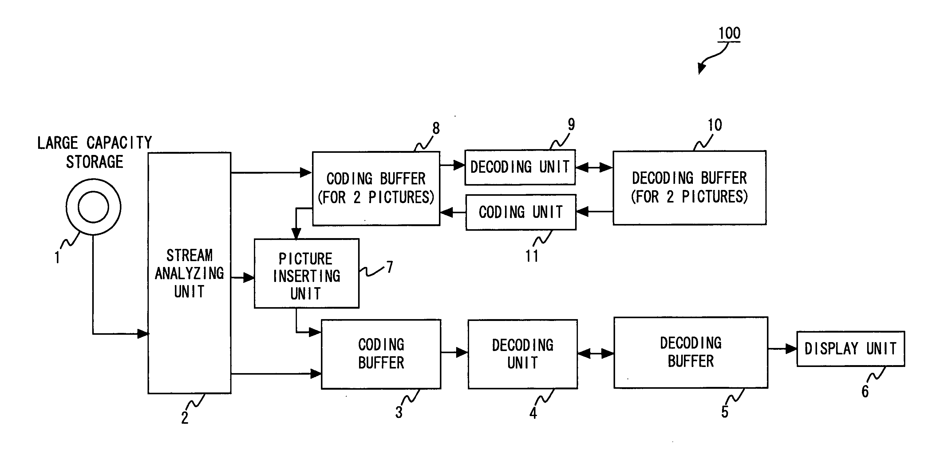
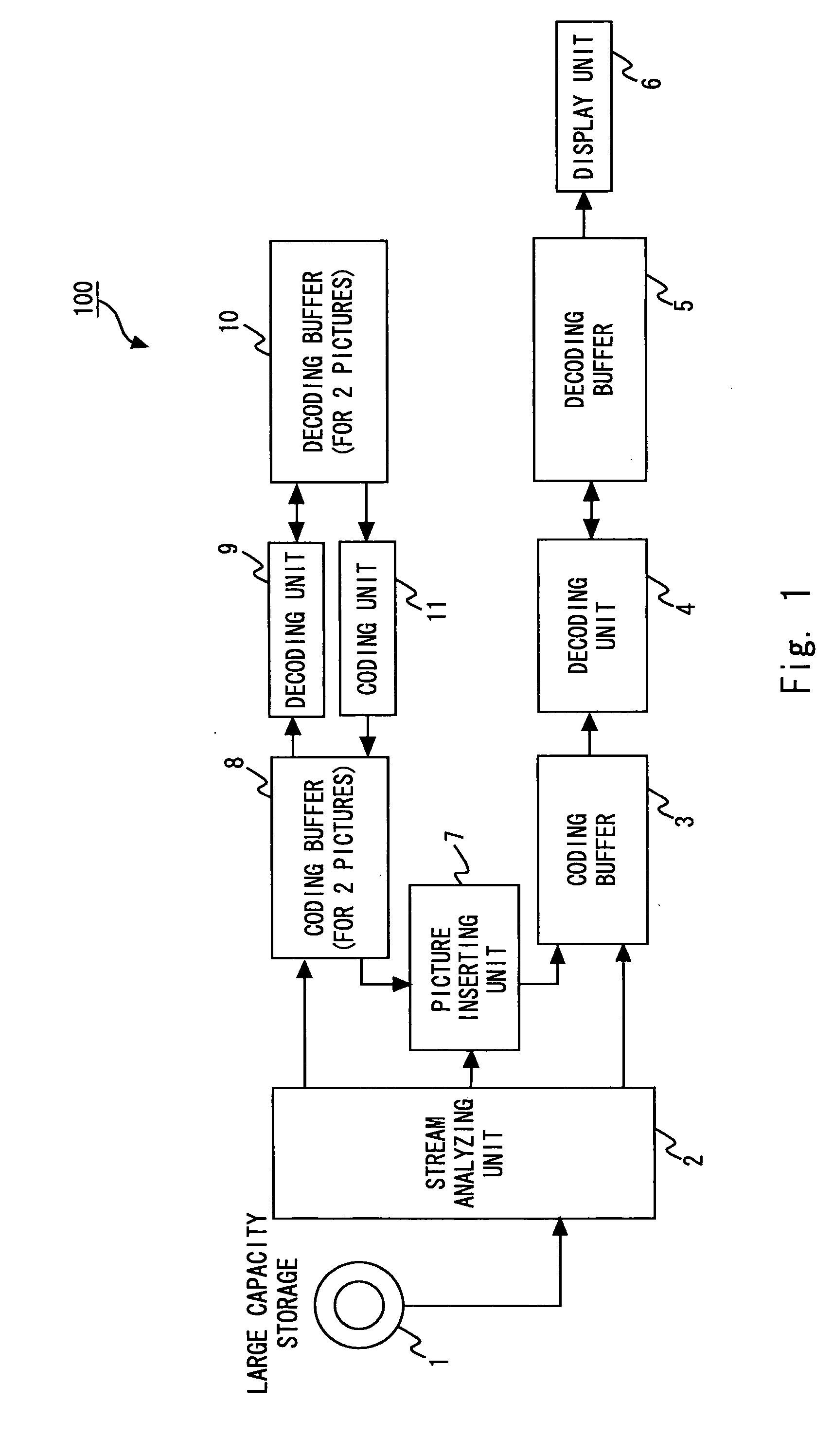
[0102]FIG. 10 is a block diagram showing an information processing apparatus according to a second embodiment of the present invention. In the first embodiment, the divided GOP includes the I picture as a core picture, but in this embodiment, the decoded picture that is decoded by the decoding unit 9 and stored in the decoding buffer 10 is directly transferred to the decoding buffer 5 to omit the recoding process and the transfer process for the I picture.
[0103] As shown in FIG. 10, the coding buffer 8 in the information processing apparatus of this embodiment 130 only needs to have a storage area enough to buffer 1 picture. Then, the decoding unit 9 for decoding the picture transferred to the coding buffer 8 is provided downstream of the coding buffer 8 similar to the first embodiment. Following the decoding unit 9, the decoding buffer 10 capable of buffering 2 pictures is provided. Here, the decoding buffer 10 of this embodiment can transfer the decoded picture to the decoding bu...
third embodiment
[0115] In the above first and second embodiments, a dividing target is a single GOP, and the GOP is divided to yield plural divided GOPs. However, plural GOPs maybe divided. In a third embodiment of the invention, the plural GOPs are assumed as one dividing-target GOP and divided using the above information processing apparatus 100, 120, and 130.
[0116]FIG. 12 shows a stream S4 having the dividing-target GOP of the third embodiment, and a stream D4 having the divided GOP. In this embodiment, the dividing-target GOP composed of the plural GOPs is divided, so the original GOP in the stream is converted into a GOP different from the original one.
[0117] The GOP includes an Open GOP that requires picture information displayed first upon the forward playback and a Closed GOP that does not require such information. In this embodiment, the same processings as the first and second embodiments are carried out to convert the Open GOP to the Closed GOP.
[0118] Next, a method of converting the ...
PUM
 Abstract
Description
Claims
Application Information
 - R&D
- Intellectual Property
- Life Sciences
- Materials
- Tech Scout
- Unparalleled Data Quality
- Higher Quality Content
- 60% Fewer Hallucinations
Browse by: Latest US Patents, China's latest patents, Technical Efficacy Thesaurus, Application Domain, Technology Topic, Popular Technical Reports.
© 2025 PatSnap. All rights reserved.Legal|Privacy policy|Modern Slavery Act Transparency Statement|Sitemap|About US| Contact US: help@patsnap.com


