
Textile heat accumulator for utilization of solar energy

Active Publication Date: 2006-11-23
PAUSE BARBARA HILDEGARD
View PDF24 Cites 6 Cited by
  • Summary
  • Abstract
  • Description
  • Claims
  • Application Information

AI Technical Summary

Benefits of technology

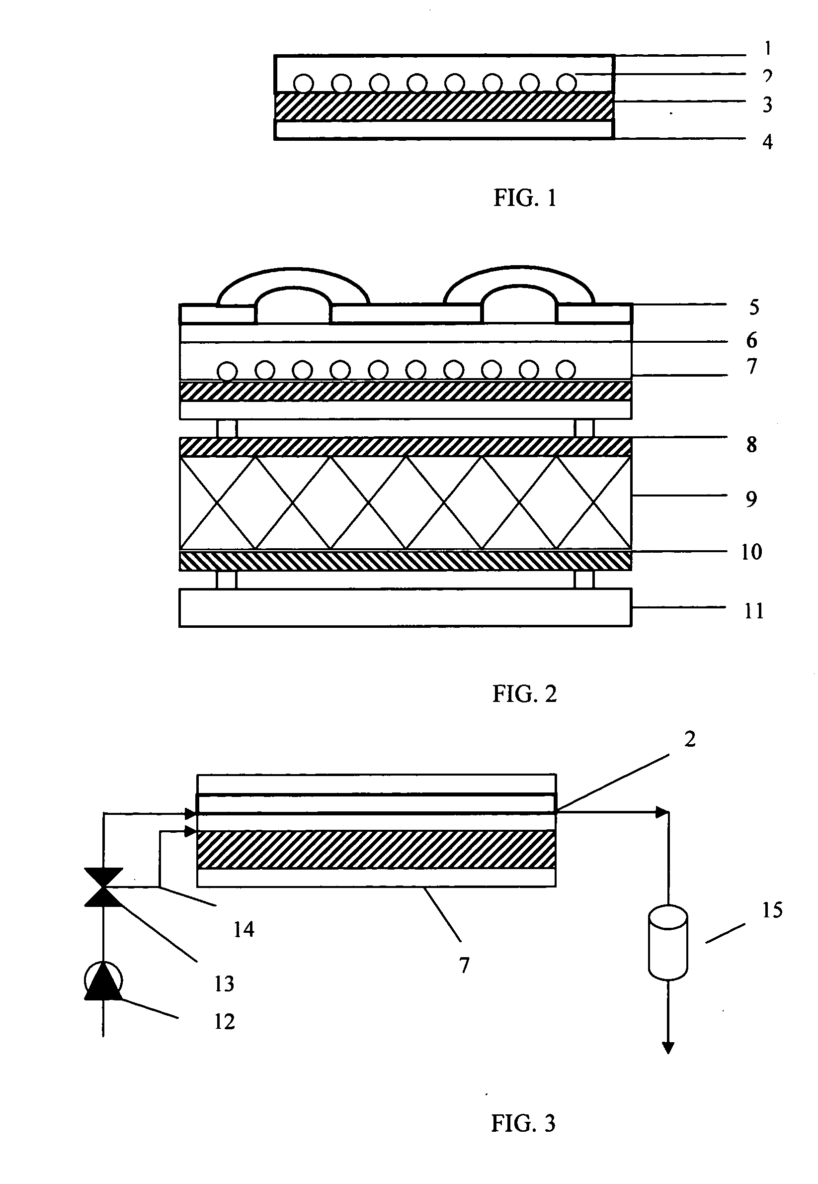
[0012] The invention pertains to a textile heat accumulator consisting of a textile composite with incorporated phase change material which is suitable for energy storage as well as hot water generation. The textile heat accumulator is preferably used in roofs of residential or commercial buildings. In its building application, the textile heat accumulator controls the heat flux into the building. In addition, the latent heat stored in the phase change material during the day is used for hot water supply. The phase change material is integrated into an elastomeric compound which is applied to a carrier fabric in form of a coating. The textile carrier is equipped with capillary pipes which are used for water transportation. In order to use the stored latent heat, cold water is pumped through the capillaries. The water absorbs the latent heat stored in the phase change material, heats up and can be used as hot water. The textile composite replaces the heat storage unit of common thermal solar energy systems. Comparing the proposed system to the common thermal solar systems, the proposed system is less expensive and does not require a lot of space. Furthermore, by recharging the phase change material during the day, the thermal performance of the phase change material is enhanced significantly.
[0013] In a preferred embodiment of the technique of the present invention, the phase change materials are non-combustible salt hydrates which allows them to meet fire-resistance requirements of building materials.

Problems solved by technology

A disadvantage of crystalline alkyl hydrocarbons is their low resistance against ignition.
Salt hydrates often show an incongruent melting behaviour as a result of a lack in reversible melting and freezing making them unsuitable for permanent use.

Method used


Image

  • Textile heat accumulator for utilization of solar energy
  • Textile heat accumulator for utilization of solar energy

Examples


Embodiment Construction

[0017] In accordance with the present application, and with reference to FIG. 1 the textile heat accumulator of the present invention includes a first layer (1), a second layer (3) and a third layer (4). The first layer is an elastomeric coating compound comprising finely divided phase change materials. The second layer is a fabric which has capillary pipes (2) attached to one of its sides. The third layer is another coating compound which does not include phase change material.

[0018] In a preferred embodiment of the textile heat accumulator, the phase change material used within absorbs latent heat when its temperature rises above 55° C.

[0019] Most preferably, the phase change material used in the textile heat accumulator is a non-combustible salt hydrate. Using a non-combustible salt hydrate in the technique of the present invention allows for compliance with fire-resistance requirements of building materials. For instance, lithium acetate dihydrate and magnesium cloride tetrahy...


PUM


Abstract

The invention relates to a textile heat accumulator consisting of a textile carrier material to which a plurality of thin capillaries for water transportation are attached and which is coated with an elastomeric compound comprising finely divided phase change materials such as salt hydrates or crystalline alkyl hydrocarbons. The textile heat accumulator arranged in a roofing structure of a building facilitates the control of the heat flux into the building and the utilization of the latent heat stored within phase change material for hot water generation.

Description

CROSS-REFERENCES TO RELATED APPLICATIONS [0001] This application claims priority of U.S. Provisional Patent Application Ser. No. 60 / 682,520 filed May 18, 2005 entitled “Utilization of solar energy with textile heat accumulators”.BACKGROUND OF THE INVENTION [0002] The worldwide increase in energy demands, the constant rise in energy prices and concerns of environmental damages caused by the increased use of fossil energy resources drives the demand for energy conservation and the use of renewable energies. The problem can be solved by the implication of textile heat accumulators based on the application of phase change material and used for hot water supply. [0003] Phase change material is a highly-productive thermal storage medium which possesses the ability to change its physical state within a certain temperature range. When the melting temperature is obtained during a heating process, the phase change from the solid to the liquid state occurs. During this melting process, the pha...

Claims


Application Information

Patent Timeline
IPC IPC(8): G03G15/32
CPCF24J2/34F24J2/48Y02B10/20Y02E60/145F28D20/023Y02E70/30Y02E10/40F24S60/10F24S60/30F24S70/10Y02E60/14
Inventor PAUSE, BARBARA HILDEGARD
Owner PAUSE BARBARA HILDEGARD
Learn More