Planer/sander wood machine

a wood machine and sandering technology, applied in the direction of grinding machines, large fixed members, milling equipments, etc., can solve the problems of heavy duty and expensive apparatuses that are not readily available outside of the commercial and industrial sphere, and the deficiency of prior art tools

Inactive Publication Date: 2006-11-16
OWEN LESLIE JOHN
View PDF3 Cites 6 Cited by
  • Summary
  • Abstract
  • Description
  • Claims
  • Application Information

AI Technical Summary

Benefits of technology

[0006] One object of the invention is to provide an improved machine tool guide.

Problems solved by technology

The machining of large pieces of wood or wood related material, particularly of a type which occur when large slabs or flitches of timber require machining, pose particular problems for the machinist if a refined or high level of machining and finish are required of the finished product of the tool.
While such machining accomplishes a task of reducing a wooden log to a series of slabs or flitches, the very nature of chainsaw mill operations and even industrial band saw mills results in a very rough and preliminary machining finish which leaves the task for the furniture builder or cabinet maker to dress the slab product into a more suitable form for production of furniture and the like.
However, such devices when put to the task of machining large dimensions of slabs of timber result in very heavy duty and expensive apparatus which is not readily available outside of the commercial and industrial sphere.
Whilst prior art machines are available for mounting cutting and sanding tools in the manner of the machine described above; when large cutting tools are used or sanding disks having a substantial surface or working area in contact with the work piece, prior art tools are often found to be deficient particularly in their inability to fine tune and very precisely align the working face of the tool in a plane corresponding precisely with the plane of the work piece in question.

Method used


Image

  • Planer/sander wood machine
  • Planer/sander wood machine
  • Planer/sander wood machine

Examples


Embodiment Construction

[0008] The invention will be described with reference to the following figures and legend.

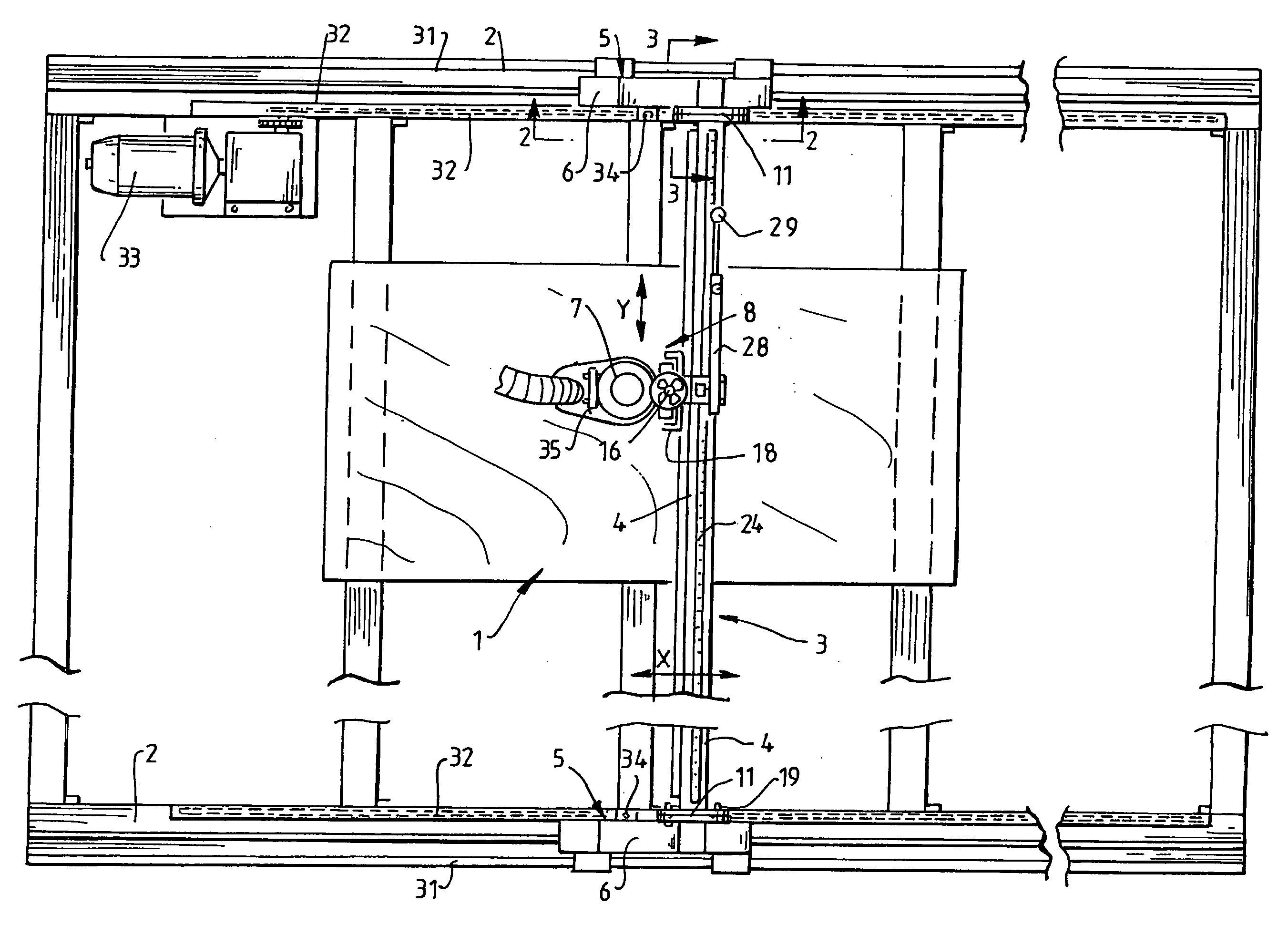
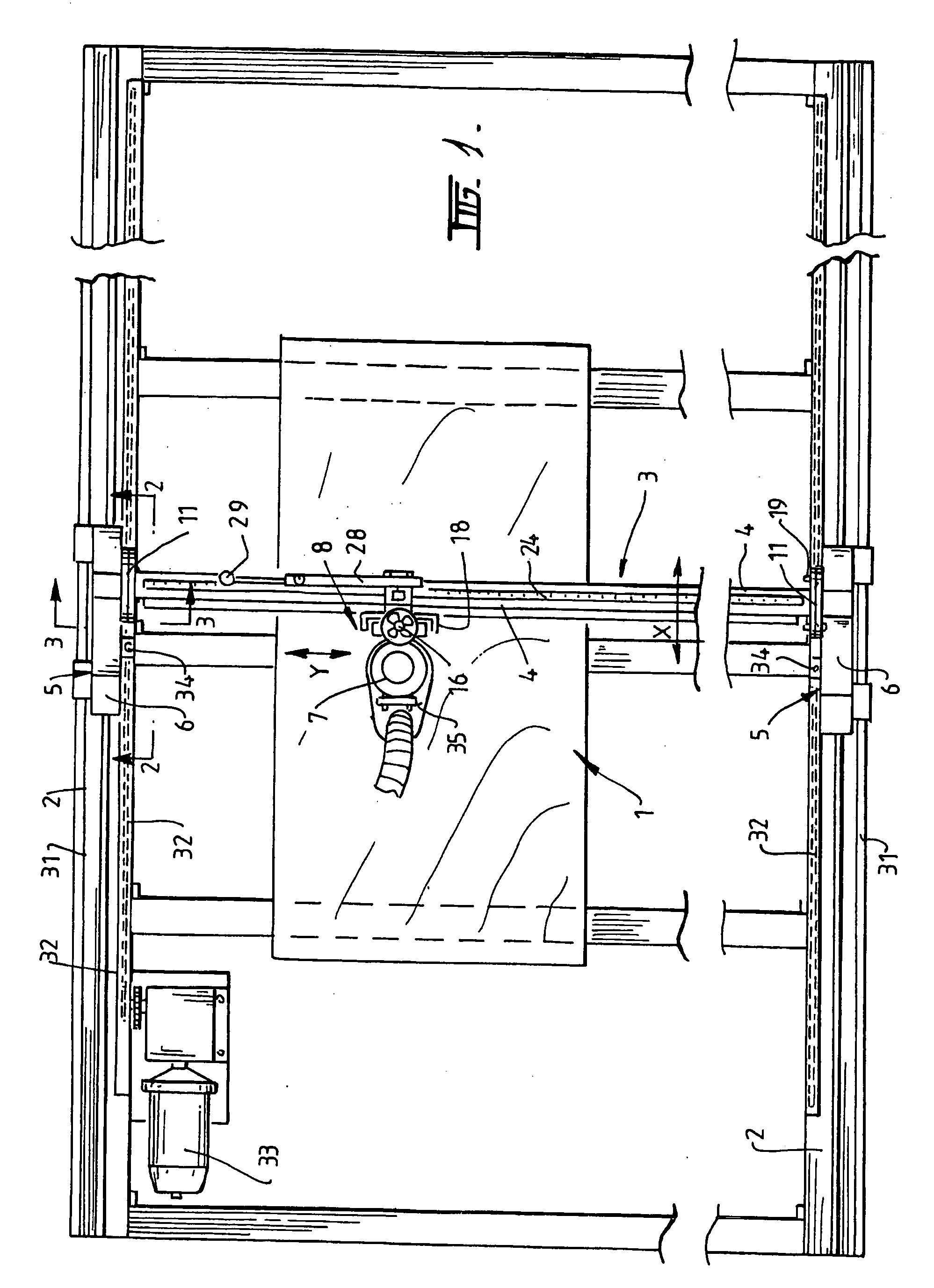
[0009]FIG. 1 Shows a plan view of the machine;

[0010]FIG. 2 Shows a side view of Gantry taken on line 2-2 on FIG. 1;

[0011]FIG. 3 Shows a sectional view taken on line 3-3 on FIG. 1 of Gantry components;

[0012]FIG. 4 Shows an enlarged plan view of the tool drive attachment to the Gantry Rail;

[0013]FIG. 5 Shows a side view taken on line 5-5 on FIG. 4 of the tool drive and attachment to the Gantry Rail;

[0014]FIG. 6 Shows a sectional plan view taken on line 6-6 on FIG. 5 showing bearing and plate arrangement;

[0015]FIG. 7 Shows a sectional view on line 7-7 on FIG. 5 illustrating means locking height adjustment;

[0016]FIG. 8 Shows a sectional plan view on line 8-8 on FIG. 7;

[0017]FIG. 9 Shows a view taken on line 9-9 on FIG. 5, showing the height adjustment for work tool;

LEGEND

[0018]1. Work piece

[0019]2. Horizontal guide rails

[0020]3. Gantry

[0021]4. Gantry rail

[0022]5. Gantry arm

[0023]6. G...


PUM

PropertyMeasurementUnit
lengthaaaaaaaaaa
poweraaaaaaaaaa
thicknessesaaaaaaaaaa

Abstract

A guide for a machine tool or tool drive (7) means for moving a surfacing tool over the substantial surface of a work piece (1), said guide comprising a guide means adapted for positioning over said work piece, said guide means including two horizontal spaced apart guide rails (2) and a gantry (3) adapted for linear travel in an X-axis along said guide rails wherein said gantry includes a gantry rail (4) adapted to bridge said spaced apart guide rails, a pair of gantry arms (5) fitted to either end of said gantry rail each gantry arm having a gantry foot for co-operating with said guide rail wherein said tool drive (7) is fitted to said gantry by a gantry mount adapted for lateral movement along the length of said gantry Y-axis, said mount including a vertical Z-axis height adjustment face plate (9) for mounting said tool drive wherein the fitting of said gantry rail to said guide rails is adjustable about said X-axis and the fitting of said tool drive to said gantry mount is adjustable about said Y-axis such that the cutting face of a tool fitted to said drive can be adjusted to correspond to the surface on planar face of said work piece without the need to clamp said work piece to said guide.

Description

CROSS-REFERENCE TO RELATED APPLICATIONS [0001] The present application claims priority from Australian Provisional Patent Application No 2005902332 filed on 9 May 2005, the content of which is incorporated herein by reference. INTRODUCTION TO THE INVENTION [0002] This invention relates to a machine tool of the type designed to service large work pieces. In particular work pieces of the type found in large slabs of timber where substantial expanses of a work piece require machining and levelling to a high degree of accuracy. BACKGROUND TO THE INVENTION [0003] The machining of large pieces of wood or wood related material, particularly of a type which occur when large slabs or flitches of timber require machining, pose particular problems for the machinist if a refined or high level of machining and finish are required of the finished product of the tool. Traditionally timber logs are prepared in a timber mill by way of large band sawing operations or small scale operations including ...

Claims


Application Information

Patent Timeline
Patent Type & Authority Applications(United States)
IPC IPC(8): B23C3/00B23C1/00
CPCB24B7/005B24B7/28Y10T409/307728Y10T409/307112B27C1/005
Inventor OWEN, LESLIE JOHN
Owner OWEN LESLIE JOHN
Why Eureka
Try Eureka