
Hollow Fiber Membrane Adsorber and Process for the Use Thereof

a technology of hollow fiber and membrane, applied in the direction of membrane technology, separation process, chemistry apparatus and process, etc., can solve the problems of increasing operating, maintenance and capital costs, membrane fouling in uf/mf, and not being competitive with conventional technology for most applications in water and wastewater treatment, so as to achieve more cost-effective effects

Inactive Publication Date: 2006-11-16
USPOLYRES
View PDF24 Cites 7 Cited by
  • Summary
  • Abstract
  • Description
  • Claims
  • Application Information

AI Technical Summary

Benefits of technology

The present invention provides a hollow-fiber membrane filtration process that is cost-effective compared to traditional methods. The process uses a membrane module consisting of hollow fiber membranes to filter liquid by collecting colloidally suspended particles on the outer surfaces of the membranes. The process has a high product recovery and can be operated at constant transmembrane pressure and constant feed flow rate using a control valve. The invention also allows for the use of membranes with high adsorptive capabilities and widened the range of polymers and other materials that can be used for hollow fibers. The filtration system can have multiple stages with the filtrate from the previous stage used as the feed for the following stage until the last stage.

Problems solved by technology

Membrane fouling in UF / MF is a problem that has been attracting considerable intellectual and engineering resources over almost 40 years.
All these efforts are associated with increased operating, maintenance, and capital costs, and, as a result, UF / MF is still not competitive with conventional technologies for most applications in water and wastewater treatment.
Unfortunately, the latter ones often do not show high mechanical strength and chemical resistance, which are required by many water treatment applications (“Membrane Handbook”.

Method used


Image

  • Hollow Fiber Membrane Adsorber and Process for the Use Thereof
  • Hollow Fiber Membrane Adsorber and Process for the Use Thereof
  • Hollow Fiber Membrane Adsorber and Process for the Use Thereof

Examples


example

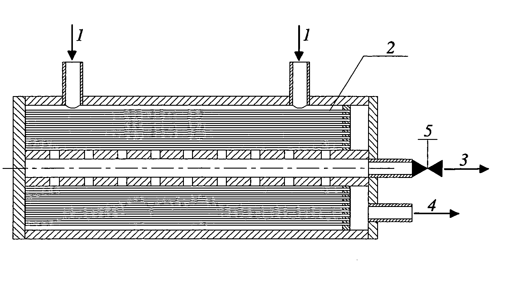
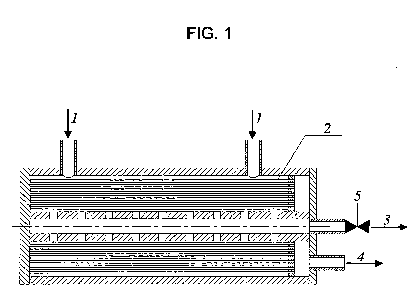
[0040] A three-stage plant with HFM adsorbers, in which the filtrate leaving the first-stage adsorber is used as the feed to the second stage adsorbers and the second-stage filtrate as the feed for the third-stage adsorber, makes it possible to achieve very high particle retentions and water recoveries (FIG. 4). For example, when the particle retention in an HFM adsorber is 90%, the second stage of the plant will provide a retention about 99%. In this plant, the permeate exiting the adsorbers can be collected in a clean product tank. Obviously, the values of water recovery that could be reached in HFM adsorbers would be as high as those in deadend HFM filters. In contrast to a plant with deadend HFM filters operated at constant pressure, in which the product flow rate declines with time, a plant with HFM adsorbers will provide a constant product flow rate at constant pressure.

[0041] The plant schematically depicted in FIG. 4 can be operated as follows.

[0042] Separation mode: Valve...


PUM


Abstract

There is disclosed a micro- or ultrafiltration process using a membrane module consisting of hollow fiber, tubular, or capillary membranes, comprising feeding the liquid to be treated in the space between the membranes; withdrawing the permeate, a product stream which is obtained by passing the liquid under the action of pressure gradient through the pores of said membranes from the outsides thereof to the insides thereof to trap the colloidally suspended particles on the outer surfaces and / or inside the pores of said membranes, from the inside of said membranes; withdrawing the filtrate, a product stream which is obtained by collection of said particles on the outside surface of said membranes due to adsorption and / or other particle collection mechanisms, under the action of pressure difference across a control valve, or any other flow control device, at the filter outlet.

Description

CROSS-REFERENCE TO RELATED APPLICATIONS [0001] This application claims the benefit of U.S. Provisional Patent Application No. 60 / 681,056 filed May 16, 2005.DESCRIPTION Terms Used in the Invention [0002] To avoid any misunderstanding of the present invention both itself and in comparison with the current state of the art, the following terms deserve explanation to be properly understood throughout this description. Definition List 1TermDefinitionA product streama stream of clarified liquid exiting a filterA permeatea product stream obtained by passing aliquid through semipermeablemembranesA filtratea product stream obtained due tocollection of suspended particles on theoutside surface (shell) of semipermeablemembranes by adsorption and / or otherparticle collection mechanismsA dead-end filtera filter with a single exit stream,permeateBACKGROUND OF THE INVENTION [0003] Microfiltration (MF) and ultrafiltration (UF), in which a semipermeable porous membrane is used to clean a slurry from...

Claims


Application Information

Patent Timeline
Patent Type & Authority Applications(United States)
IPC IPC(8): B01D61/00
CPCB01D61/142B01D61/145C02F1/444B01D61/20B01D61/147B01D61/149
Inventor POLYAKOV, YURIY S.
Owner USPOLYRES
Learn More