Ground shield structure

a shield structure and ground shield technology, applied in printed circuits, printed circuit details, electrical devices, etc., can solve the problem that the ground shield cannot be used for the other microwave transmission device, and achieve the effect of reducing the area of the circuit layout, reducing the energy loss of the inner circuit, and reducing the eddy curren

Inactive Publication Date: 2006-11-16
SZE BOURYI +3
View PDF3 Cites 13 Cited by
  • Summary
  • Abstract
  • Description
  • Claims
  • Application Information

AI Technical Summary

Benefits of technology

[0010] The invention provides a ground shield structure, suitable for use of increasing the slow-wave factor, so that the wave can slowly propagate and the needed area for the circuit layout is effectively reduced.
[0011] The invention further provides a ground shield structure, for increasing the inductance quantity and capacitance quantity of the ground shield structure in a unit area.
[0013] In accordance with the foregoing features, the ground shield structure is suitable for use in a circuit structure. The ground shield structure has a plurality of ground cells that are arranged on a ground plane periodically, compactly and complementarily. The slots between the ground cells are used to reduce the eddy current generated on the ground shield structure. The ground shield structure increases the slow-wave factor to slow the waves so that the area of the circuit layout can be decreased. Besides, the ground shield structure can reduce the energy loss of the inner circuit of the circuit structure and can increase the quantities of inductance and capacitance in per unit area thereon.

Problems solved by technology

It cannot serve as the ground shield for the other microwave transmission device, such as transmission line, wave-guide, power divider, directional coupler, or microwave filter.

Method used


Image

  • Ground shield structure
  • Ground shield structure
  • Ground shield structure

Examples


Embodiment Construction

[0021] The ground shield structure of the invention is suitable for use in a circuit structure, such as an integrated circuit, a printed circuit board, a chip package substrate, or other electronic devices, so as to provide the shielding function.

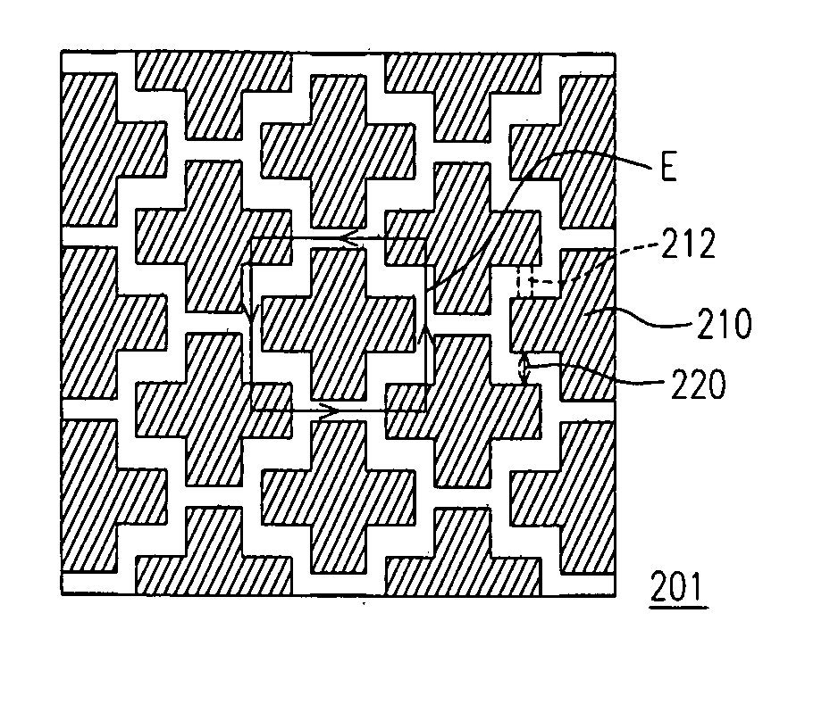
[0022] In FIG. 2A, a ground shield structure is shown, according to the invention. The ground shield structure 201 includes several ground cells 210, with identical profile, like a symbol of “+”. The ground cells 210 are distributed on a ground surface with a periodically and compactly complementary arrangement, wherein a slot 220 exists between two adjacent ground cells 210. It should be noted that the ground surface with the ground cells 210 is not limited to a planar surface. A curved surface is also applicable.

[0023] In addition, in order to electrically connect with the ground cells 210 and allow the ground cells 210 to be able to form a ground shield, the ground shield structure 201 further includes several interconnection members 2...


PUM


Abstract

The invention is directed to an electric device featuring a ground shield structure. The electric device at lease comprises a plurality of first ground cells and a plurality of second ground cells. The first ground cells are distributed on a ground surface, wherein the first ground cell has at least one first outward section and at least one first inward section. The second ground cells are distributed on the ground surface, wherein the second ground cell has at least one second outward section and one second outward section of one second ground cell is compactly and complementarily embraced by one first inward section of one adjacent first ground cell.

Description

CROSS-REFERENCE TO RELATED APPLICATION [0001] This application is a continuation-in-part of a prior application Ser. No. 10 / 681,471, filed Oct. 7, 2003. The prior application Ser. No. 10 / 681,471 claims the priority benefit of Taiwan application serial no. 92213288, filed on Jul. 21, 2003. All disclosure of the Taiwan application is incorporated herein by reference.BACKGROUND OF THE INVENTION [0002] 1. Field of Invention [0003] The present invention relates to a ground shield structure. More particularly, the present invention relates to a compact and complementary ground shield structure (CCGSS) by a periodic arrangement. [0004] 2. Description of Related Art [0005] In recent years, electronic techniques have been greatly and promptly developed. Particularly, since the semiconductor fabrication has been greatly developed, the integration for an integrated circuit (IC) device is continuously improved. Then, the size of an IC device is greatly reduced. Similarly, since the integration ...

Claims


Application Information

Patent Timeline
Patent Type & Authority Applications(United States)
IPC IPC(8): H05K9/00H05K1/02
CPCH05K1/0227H05K2201/09681H05K9/0039
Inventor SZE, BOURYICHENG, BOBHO, CHIH-LONGKAO, FELIX
Owner SZE BOURYI
Why Eureka
Try Eureka