
Auxiliary communication interface system and method thereof

a communication interface and auxiliary technology, applied in the field of communication interface devices and methods, can solve the problems of disadvantageous duplication of i/o interfaces by methods and practical limitations, and achieve the effect of effectively incorporating auxiliary equipment and avoiding costly duplication of auxiliary i/o boards

Inactive Publication Date: 2006-11-09
KACHNIC EDWARD +1
View PDF11 Cites 1 Cited by
  • Summary
  • Abstract
  • Description
  • Claims
  • Application Information

AI Technical Summary

Benefits of technology

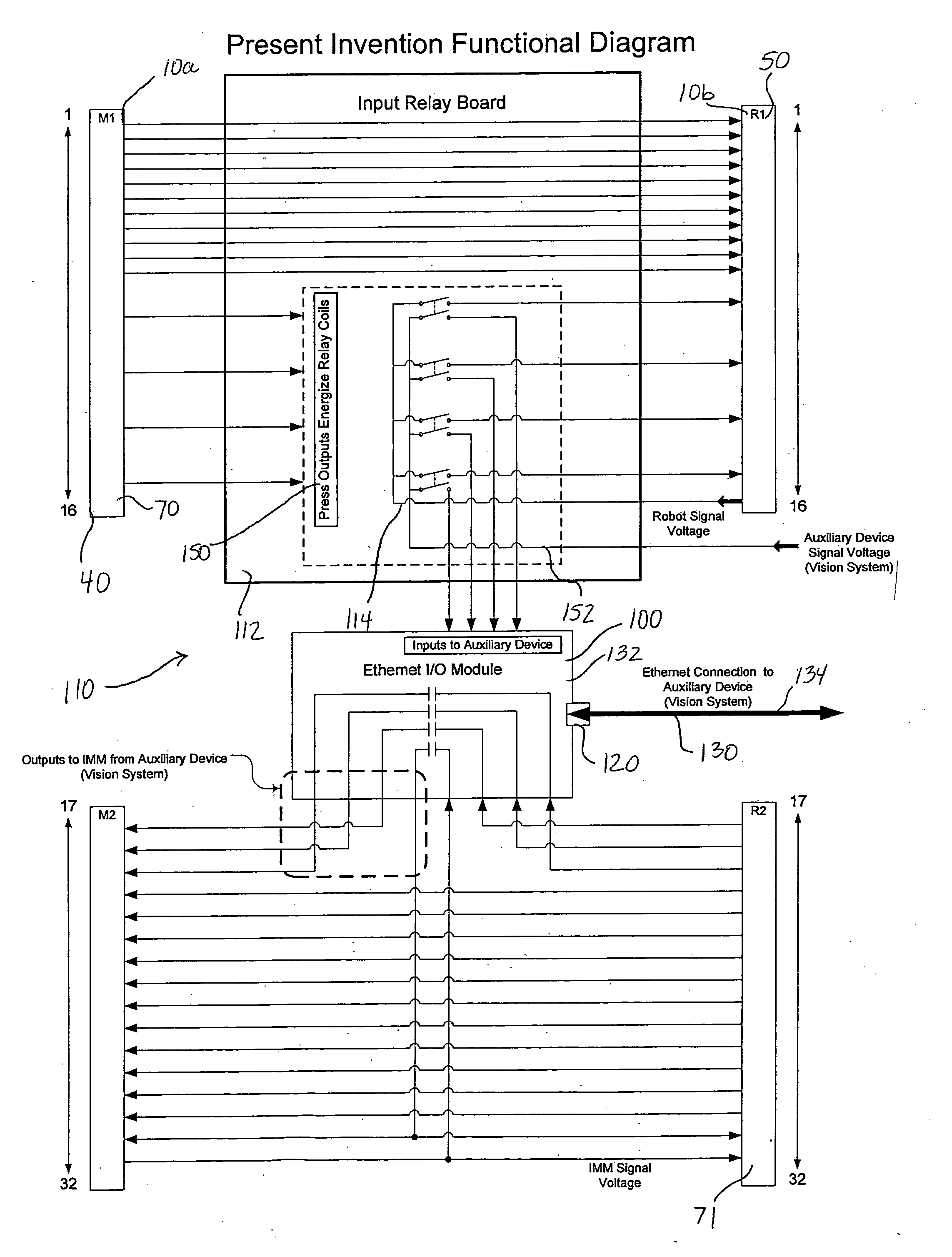
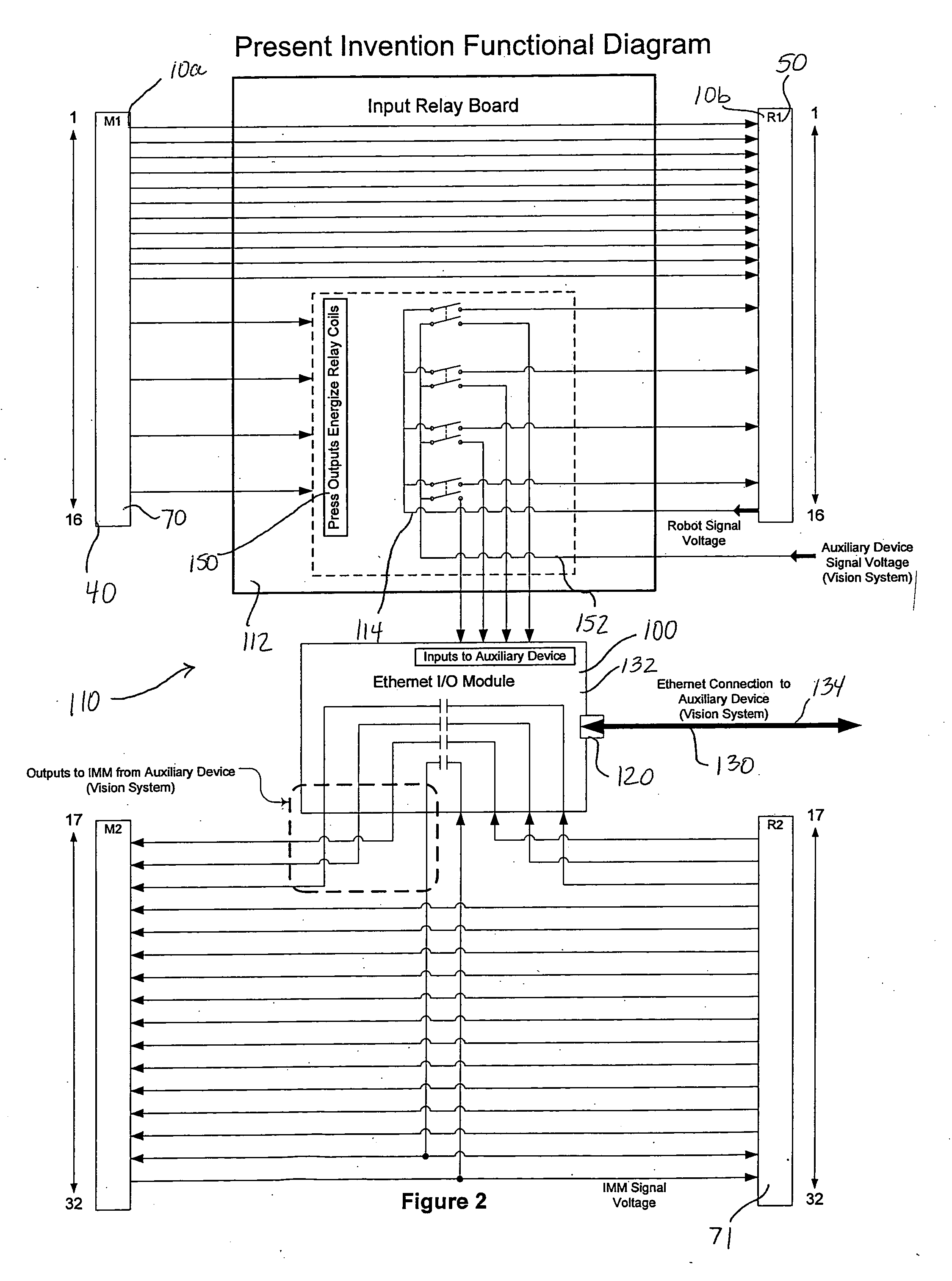
[0011] Thus, a feature and advantage of the present invention is the ability of such a method and device to enable auxiliary equipment to utilize a standardized interface between a machine controller and robot controller for communication while successfully maintaining electrical isolation therebetween.
[0012] Another feature and advantage of the present invention is the ability of such a method and device to enable isolated, concurrent signal flow to more than one component in a machine system.
[0013] Another feature and advantage of the present invention is the ability of such a method and device to eliminate costly duplication of auxiliary I / O boards.
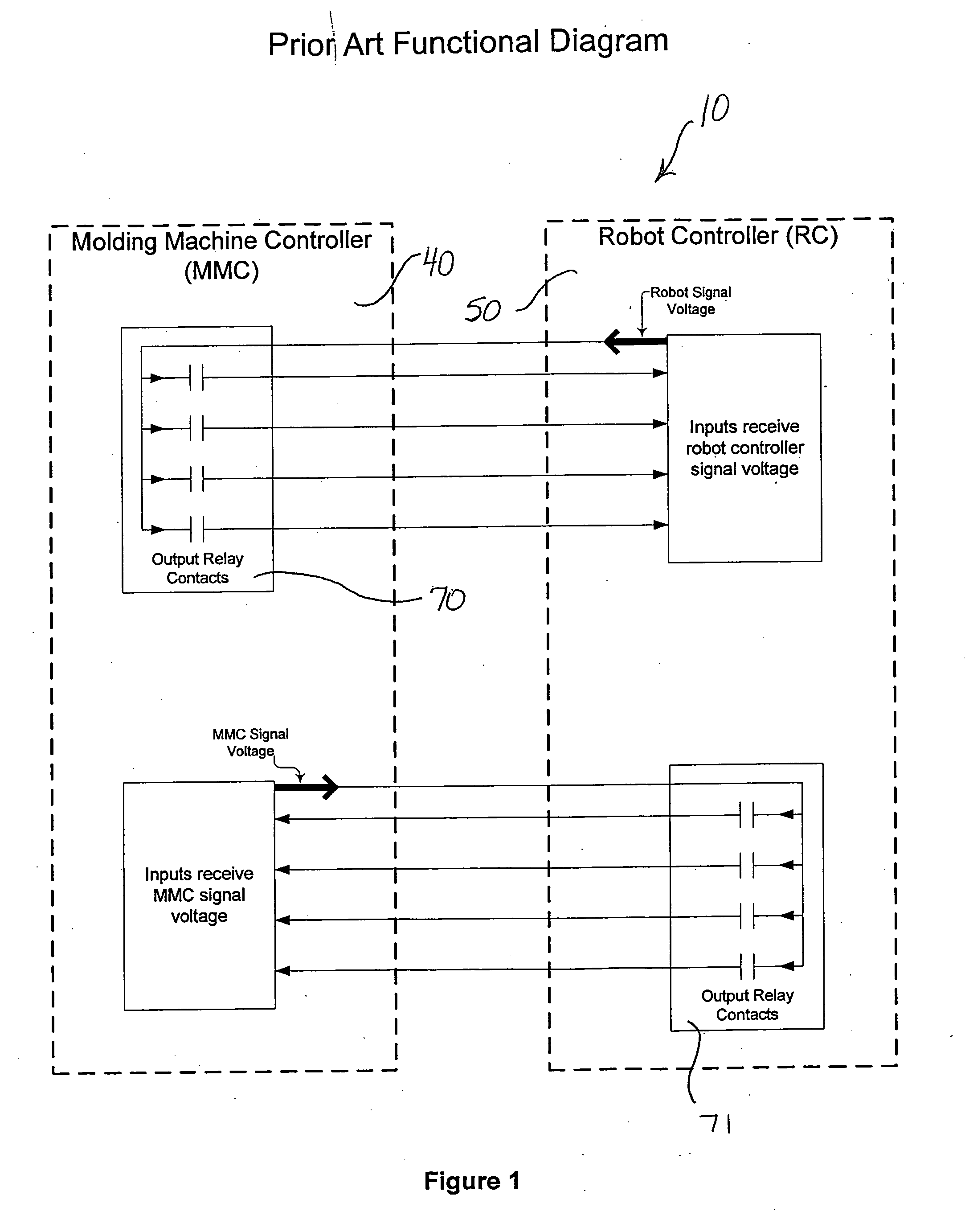
[0014] Another feature and advantage of the present invention is the ability of such a method and device to maintain a standardized SPI and EUROMAP 32-pin interface between a molding machine controller and a robot controller.
[0015] Another feature and advantage of the present invention is the ability of such a method and device to effectively incorporate auxiliary equipment into the preexisting, standardized part-forming machine controller and robot controller interface for communication, while successfully maintaining electrical isolation between each component.

Problems solved by technology

This methodology disadvantageously duplicates I / O interfaces.
Further, while each robotic implementation and sensory improvement can and does increase quality and productivity for part-forming processes, as well as other machine applications, resultant complexities in communications and attendant electrical risks between components introduce practical limitations.

Method used


Image

  • Auxiliary communication interface system and method thereof
  • Auxiliary communication interface system and method thereof
  • Auxiliary communication interface system and method thereof

Examples


Embodiment Construction

[0026] In describing the preferred and alternate embodiments of the present invention, as illustrated in the figures and / or described herein, specific terminology is employed for the sake of clarity. The invention, however, is not intended to be limited to the specific terminology so selected, and it is to be understood that each specific element includes all technical equivalents that operate in a similar manner to accomplish similar functions.

[0027] To better understand the present system and method of this invention, it will be specifically explained in the context of a particular machine system, that is, its preferred use in conjunction with an injection molding system. However, it is expressly understood and contemplated that the auxiliary communication interface system and method described herein is suitable for utilization in combination with any machine part-molding method, such as, for exemplary purposes only, stretch-blow molding, extrusion blow molding, vacuum molding, r...


PUM


Abstract

An auxiliary communication system and method, wherein system components can be electrically isolated, wherein a machine controller and a robot can communicate according to standard protocols, and wherein auxiliary equipment can be incorporated into the communication system, thereby alleviating the need for and the voltage limitations of auxiliary I / O boards.

Description

TECHNICAL FIELD [0001] The present invention relates generally to communication interface devices and methods, and more specifically, to an auxiliary communication interface system and method for enabling auxiliary equipment to utilize a standardized interface between a part-forming machine controller and robot controller for communication while successfully maintaining electrical isolation of the auxiliary equipment, the machine controller and the robot controller. BACKGROUND OF THE INVENTION [0002] Formed parts are generally created via molds, dies and / or by thermal shaping, wherein the use of molds remains the most widely utilized. There are many methods of forming a part via a mold, such as, for exemplary purposes only, stretch-blow molding, extrusion blow molding, vacuum molding, rotary molding and injection molding. Injection molding is one of the most popular methods and is a method wherein the utilization of auxiliary equipment, such as machine vision methodology, can increa...

Claims


Application Information

Patent Timeline
Patent Type & Authority Applications(United States)
IPC IPC(8): G06F19/00
CPCG05B19/0423G05B2219/21014G05B2219/2624G05B2219/25192G05B2219/25174
Inventor KACHNIC, EDWARDSCARBROUGH, LARRY
Owner KACHNIC EDWARD
Learn More