
Low resistance irrigation system and apparatus

a low-resistance, irrigation system technology, applied in the field of cataract surgery, can solve the problems of eye stability decline, tight wounds that squeeze the irrigating sleeves, vision deterioration, etc., to reduce the flow resistance of irrigation fluid, increase the diameter of irrigation fluid tubing, and reduce the effect of irrigation flow resistan

Inactive Publication Date: 2006-11-09
ALCON INC
View PDF28 Cites 12 Cited by
  • Summary
  • Abstract
  • Description
  • Claims
  • Application Information

AI Technical Summary

Benefits of technology

[0010] The present invention improves upon the prior art by providing a surgical irrigation system having reduced irrigation flow resistance. Reduction in irrigation fluid flow resistance is achieved by increasing the diameter of the irrigation fluid tubings. The ends of the tubings are tapered to reduce the stiffness of the tubings and to allow the tubings to be connected to current surgical devices.
[0011] Accordingly, one objective of the present invention is to provide a surgical irrigation system having reduced irrigation flow resistance.
[0012] Another objective of the present invention is to provide a surgical irrigation system having more stable intraocular pressures.
[0013] Another objective of the present invention is to provide a surgical irrigation system that allows for higher aspiration vacuum.
[0014] Another objective of the present invention is to provide a surgical irrigation system that allows for higher aspiration flow.

Problems solved by technology

When age or disease causes the lens to become less transparent, vision deteriorates because of the diminished light which can be transmitted to the retina.
These small incisions result in very tight wounds that squeeze the irrigating sleeve.
Such a tight wound construction decreases the stability of the eye, particularly when high aspiration vacuums (above 500 mm Hg) and / or high flows (in excess of 40 cc / min.) are used, because changes in the irrigation flow caused by either changes in the aspiration flow rate or by rapid changes in aspiration vacuum cannot be damped by the inflow of irrigation fluid, which is restricted.
Theoretically, increasing the amount of irrigating fluid entering the eye will help to stabilize the intraocular pressure (“IOP”); however, in a clinical setting, the amount of irrigation fluid entering the eye is limited to the amount of fluid aspirated from the eye due to the tight wound construction with minimal leakage from the wound.
Also, increasing the flow of irrigating fluid through the eye increases the turbulence in the eye, possibly leading to endothelial cell loss, postoperative inflammation and edema.

Method used


Image

  • Low resistance irrigation system and apparatus
  • Low resistance irrigation system and apparatus
  • Low resistance irrigation system and apparatus

Examples


Embodiment Construction

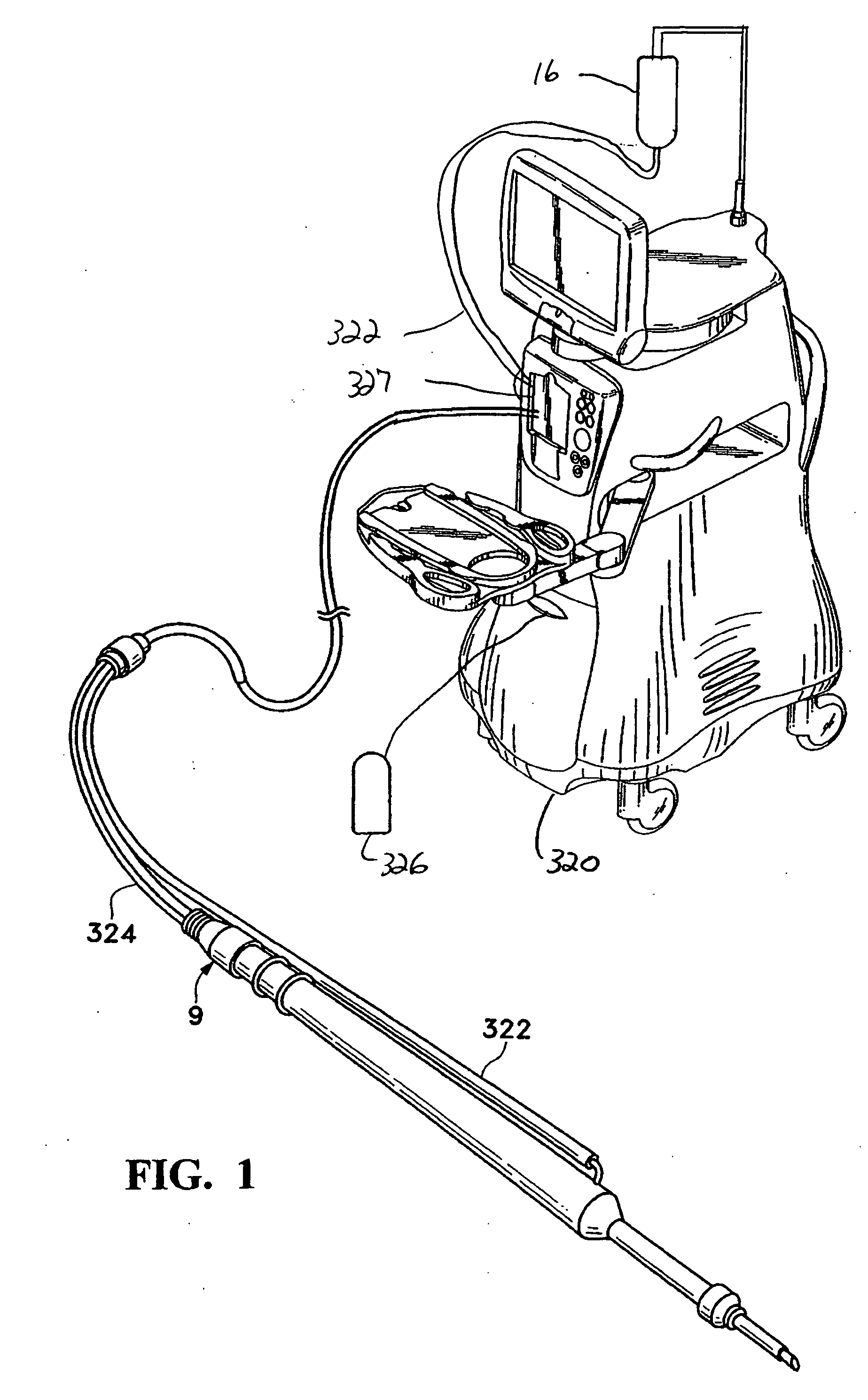
[0019] As best seen in FIG. 1, surgical console 320 suitable for use with the present invention may be any commercially available surgical control console such as the INFINITI® surgical systems available from Alcon Laboratories, Inc., Fort Worth, Tex. Console 320 is connected to handpiece 9 through irrigation line 322 and aspiration line 324, and the flow through lines 322 and 324 is controlled by the user, for example, via footswitch 326.

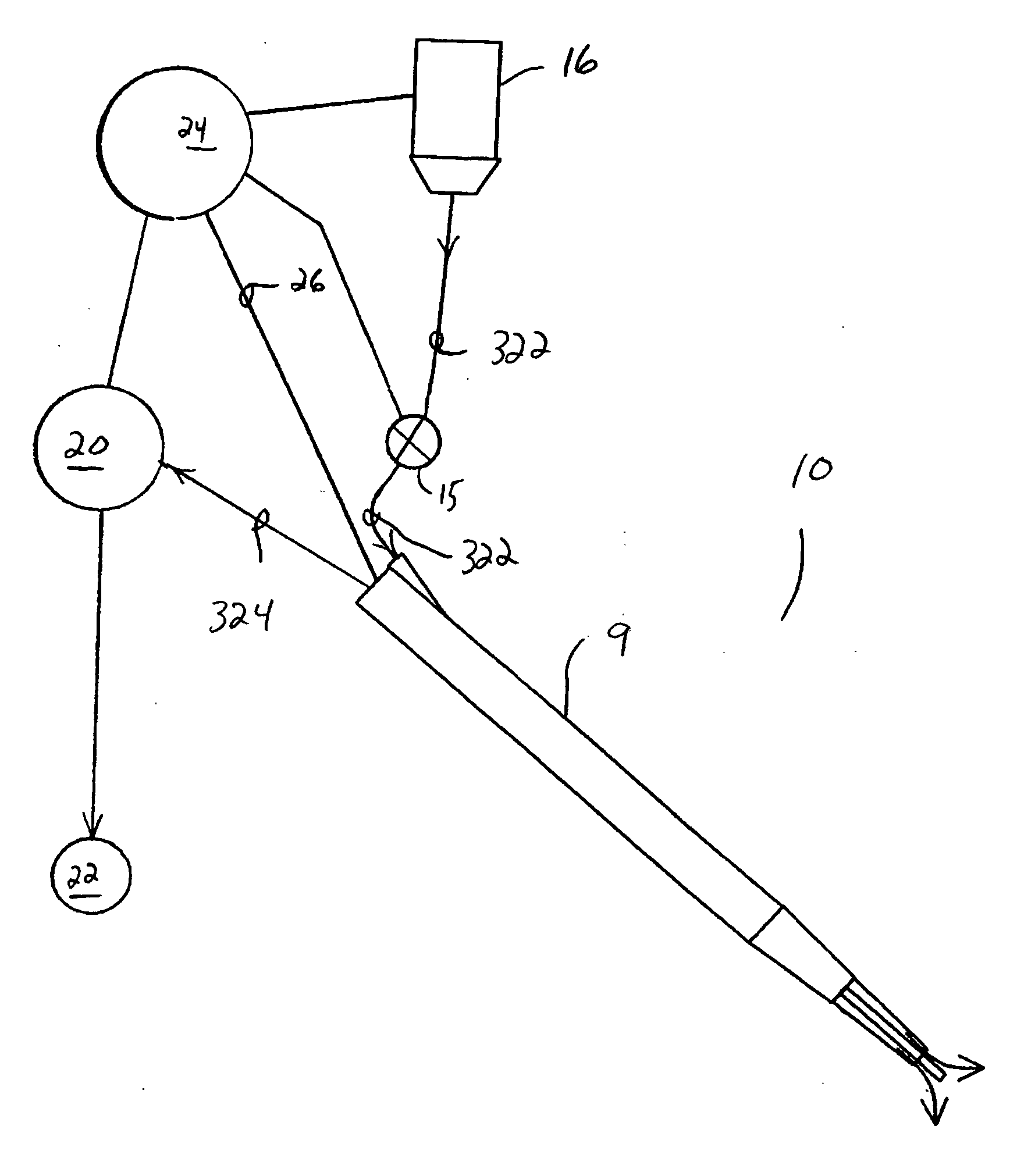
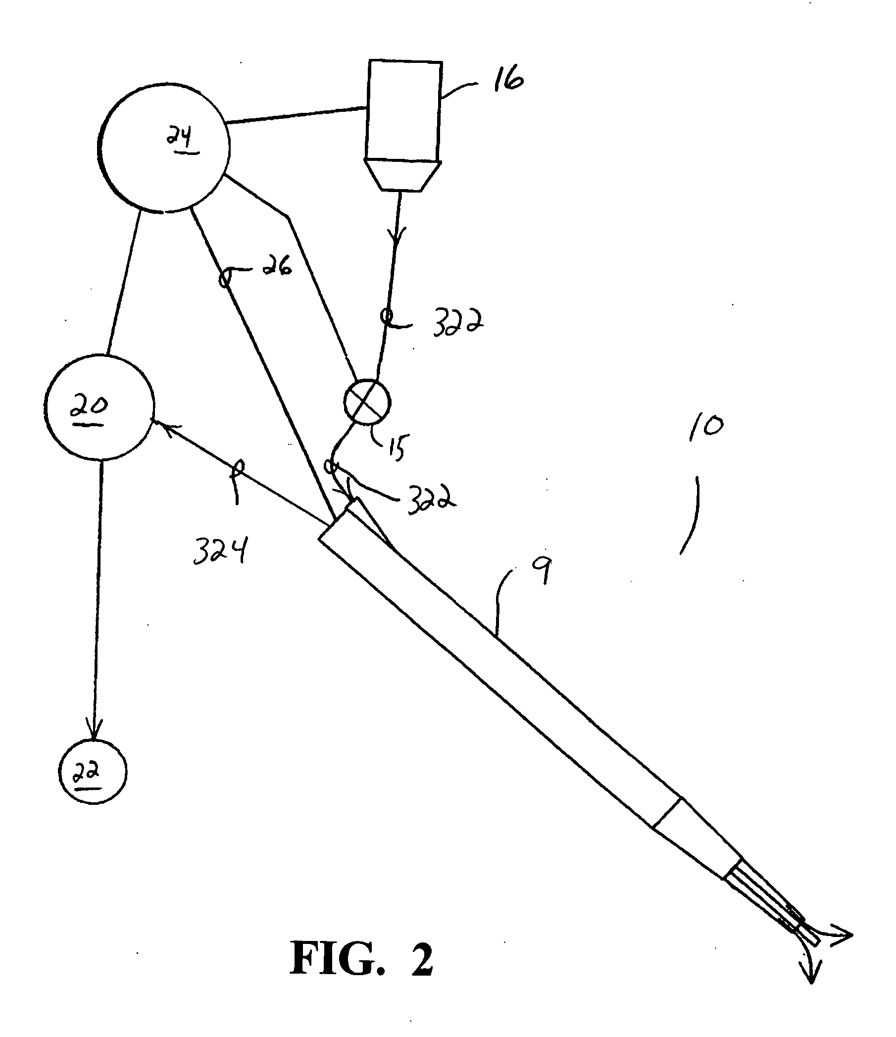
[0020] As seen in FIG. 2, schematically, system 10 embodied in console 320 that may be used in the present invention generally included handpiece 9, which is supplied with irrigating fluid through tubings 322 from source 16. Tubings 322 may contain check valve 15 or some other suitable device for controlling the flow of irrigating fluid in tubings 322. The infusion fluid from source 16 is pressurized either by gravity or by pressurizing source 16. Aspiration line 324 fluidly connects handpiece 12 to pump 20, which aspiration fluid for a surgical s...


PUM


Abstract

A surgical irrigation system having reduced irrigation flow resistance. Reduction in irrigation fluid flow resistance is achieved by increasing the diameter of the irrigation fluid tubings. The ends of the tubings are tapered to reduce the stiffness of the tubings and to allow the tubings to be connected to current surgical devices.

Description

BACKGROUND OF THE INVENTION [0001] This invention relates generally to the field of cataract surgery and more particularly to a control system for a phacoemulsification handpiece. [0002] The human eye in its simplest terms functions to provide vision by transmitting light through a clear outer portion called the cornea, and focusing the image by way of the lens onto the retina. The quality of the focused image depends on many factors including the size and shape of the eye, and the transparency of the cornea and lens. [0003] When age or disease causes the lens to become less transparent, vision deteriorates because of the diminished light which can be transmitted to the retina. This deficiency in the lens of the eye is medically known as a cataract. An accepted treatment for this condition is surgical removal of the lens and replacement of the lens function by an artificial intraocular lens (IOL). [0004] In the United States, the majority of cataractous lenses are removed by a surgi...

Claims


Application Information

Patent Timeline
IPC IPC(8): A61M1/00
CPCA61F9/00745A61M2210/0612A61M2205/12A61M3/0279A61B17/22A61B17/32A61B18/24A61M1/00A61M3/022A61M3/0208A61M3/0212A61M3/0201
Inventor LIAO, GRACE C.BRODY, GEORGEOLIVEIRA, MEL M.
Owner ALCON INC
Learn More