Eureka AIR delivers breakthrough ideas for toughest innovation challenges, trusted by R&D personnel around the world.

Joint for operatively coupling a contoured inner compression member and an inner guide channel member for medical device delivery systems

a compression member and contoured technology, applied in the field of joint assembly for operative coupling an inner compression member and an inner guide channel member, can solve the problems of increasing requiring some form of mechanical fastener, and confusing the goal of minimizing the distal end profil

Inactive Publication Date: 2006-11-02
COOK INC
View PDF55 Cites 106 Cited by
  • Summary
  • Abstract
  • Description
  • Claims
  • Application Information

AI Technical Summary

Problems solved by technology

A challenge in designing a delivery system in the rapid exchange delivery system is that the handle portion is the only interface through which the operator can control the working parts, and the inner compression member for use with the system typically forms the only connection to the inner guide channel member sometimes 50.0 centimeters and often as much or more than 125 centimeters distal to the handle portion.
Unfortunately, the full lap joint increases the profile of the distal end.
Thus, half lap joints require that each member be cut to a complementary surface, which is an arduous task in view of the already small thickness of the inner compression member and thin walls of the inner guide channel member.
Another problem with the mechanical lap joint is that it requires some form of mechanical fastener to be effective.
Moreover, the fastener adds to the profile of the two members and the fastener, and thereby confounds the goal of minimizing the profile of the distal end.
Another drawback to the fastener in a mechanical lap joint connection is the propensity to lose the friction fit between the members.
In addition, the point attachments that are typically formed by these joints could cause joint failure due to inadequate stress distribution, and may detach when a torque-load is applied.

Method used


Image

  • Joint for operatively coupling a contoured inner compression member and an inner guide channel member for medical device delivery systems
  • Joint for operatively coupling a contoured inner compression member and an inner guide channel member for medical device delivery systems
  • Joint for operatively coupling a contoured inner compression member and an inner guide channel member for medical device delivery systems

Examples


Embodiment Construction

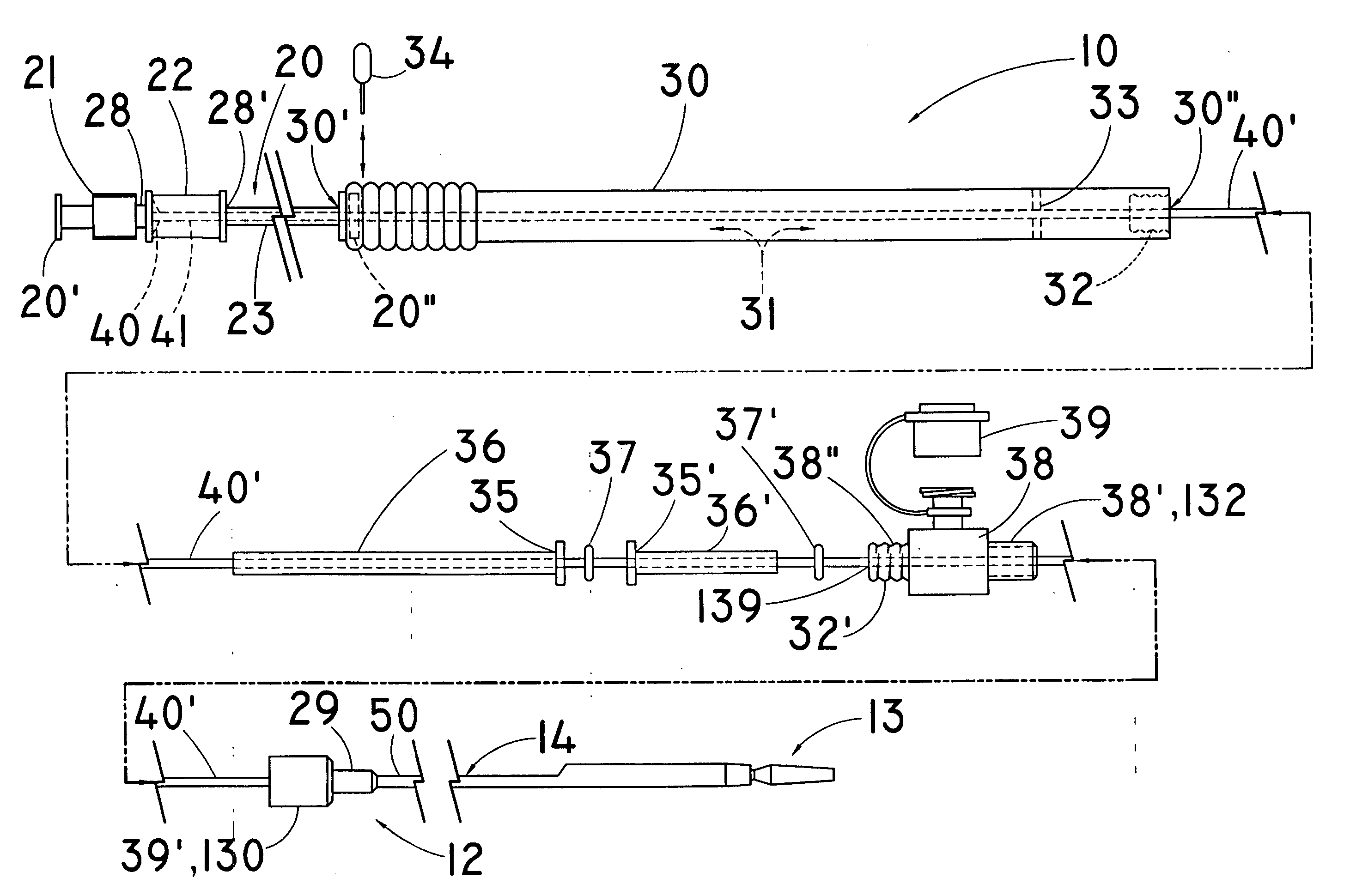
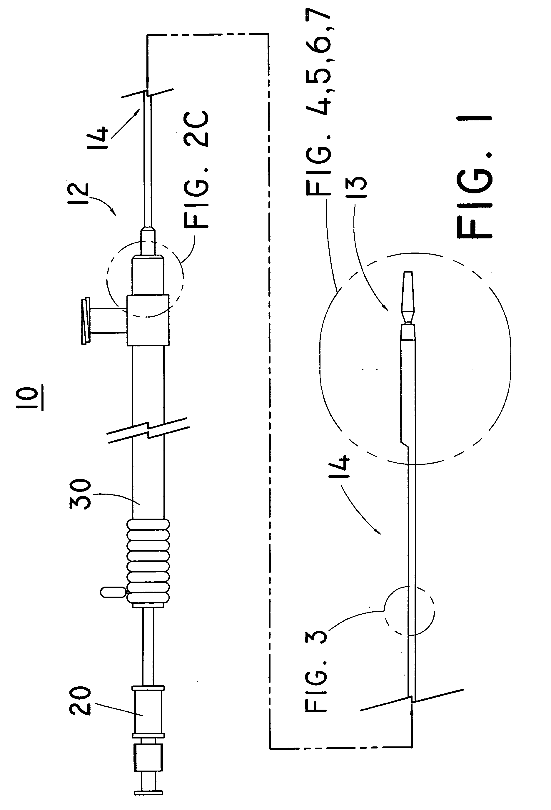
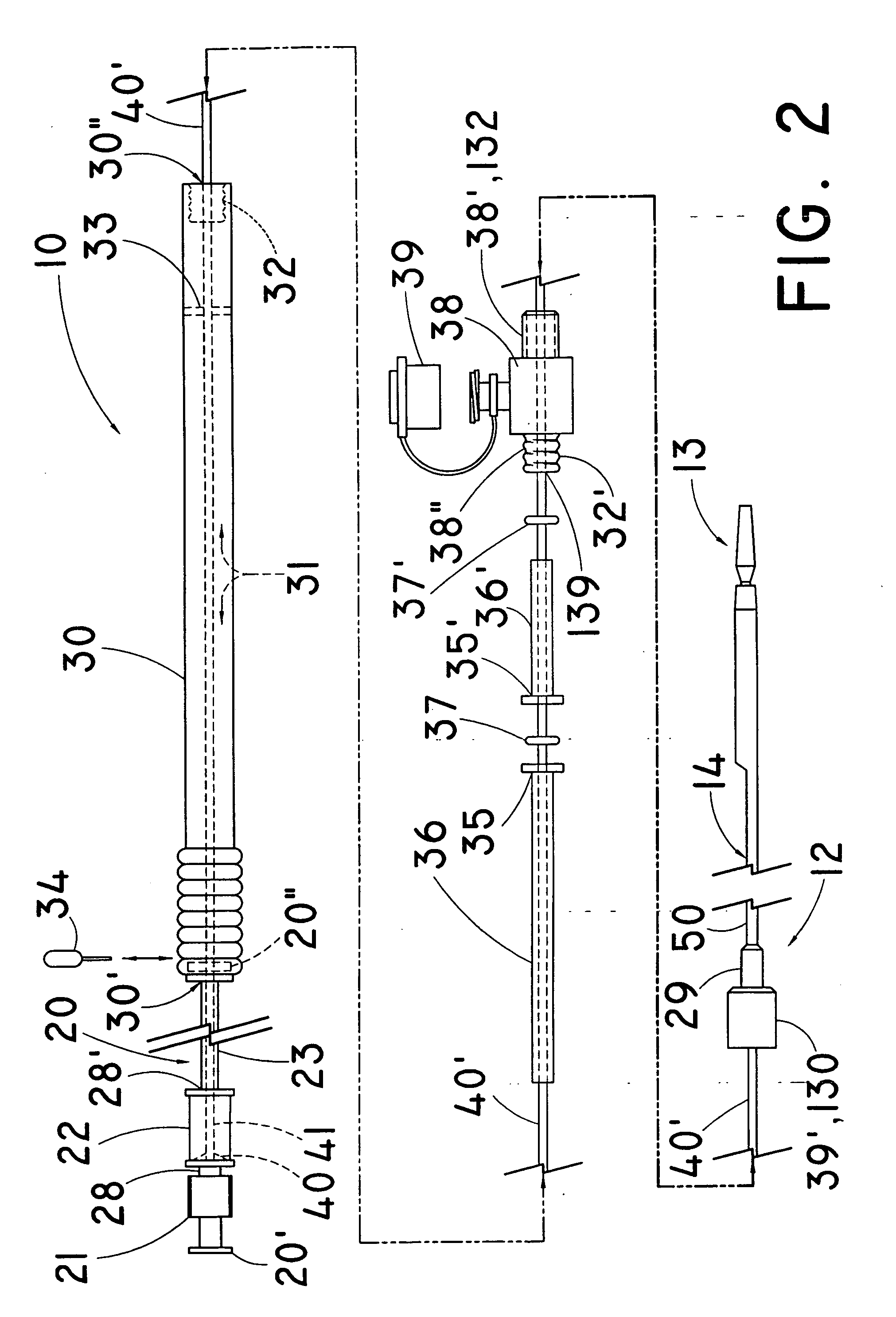
[0052] The present invention relates to medical devices, and in particular to an inner guide channel member assembly and to a joint assembly comprising a securing body operatively coupled to the inner guide channel member and an inner compression member joint assembly an inner compression member and also operatively coupling a low-profiled inner compression member for use in rapid insertion medical device delivery systems (e.g., “rapid insertion” catheters) configured for deploying expandable metallic, polymeric, and plastic devices or non-expanding metallic, polymeric, and plastic devices, which devices may include, by way of example and not by way of limitation, stents, prosthetic valve devices, and other implantable articles at selected locations inside a patient's body. For conciseness and ease of description of the embodiments of the invention, the term “stent” and its variations shall refer individually and collectively (without limiting the invention) to all self-expanding, b...


PUM

PropertyMeasurementUnit
Shrinkageaaaaaaaaaa
Diameteraaaaaaaaaa

Abstract

Internal joints for medical device delivery systems to deploy implantable prostheses at a selected location inside a patient's body, and methods of making the joint, are provided. An inner guide channel member has first and second ends, whereby the second end has an outer diameter and outer surface. A cannulated securing body has an inner securing section with a receiving cavity being sized to receive the inner guide channel member second end outer diameter and having an inner engaging surface operatively coupling to the inner guide channel member second end outer surface. The cannulated securing body further having a base securing section with an outer engaging surface. An elongate inner compression member has a distal mating end with an engaging surface having a contoured configuration complementary to and disposed against the base securing section outer engaging surface, wherein the base securing section and distal mating end are operatively coupled.

Description

RELATED APPLICATIONS [0001] The present patent document claims the benefit of the filing date under 35 U.S.C. §119(e) of Provisional U.S. Patent Application Ser. No. 60 / 673,199, filed Apr. 20, 2005, which is hereby incorporated by reference in its entirety.FIELD OF THE INVENTION [0002] The present invention relates generally to a joint assembly for operatively coupling an inner compression member and an inner guide channel member used for medical device delivery systems that deploy an implantable prosthesis such as self-expanding, balloon expandable, or non-expanding stents, prosthetic valve devices, and other implantable articles (individually and collectively, “stent,”“stents,”“implantable prosthesis,” and “implantable prostheses”) at a selected location inside a patient's body. BACKGROUND OF THE INVENTION [0003] This invention relates generally to medical device delivery systems, and in particular, to a joint assembly operatively coupling an inner compression member and an inner ...

Claims


Application Information

Patent Timeline
IPC IPC(8): A61F2/84
CPCA61F2/95A61F2002/9517A61M25/0662A61M25/005A61M25/0053A61M25/0045A61F2/9517A61F2/82
Inventor RICHARDS, KATHRYN E.MELSHEIMER, JEFFRY S.PAL, DHARMENDRA
Owner COOK INC
Why Eureka
Eureka Blog
Learn More