
System and method for detecting a condition indicative of plugging of a discharge path of an agricultural combine

a technology of detecting system and method, applied in the field of system and method for detecting condition indicative of plugging path, can solve the problems of affecting the operation of machinery, affecting the quality of machinery,

Active Publication Date: 2006-11-02
BLUE LEAF I P
View PDF33 Cites 20 Cited by
  • Summary
  • Abstract
  • Description
  • Claims
  • Application Information

AI Technical Summary

Benefits of technology

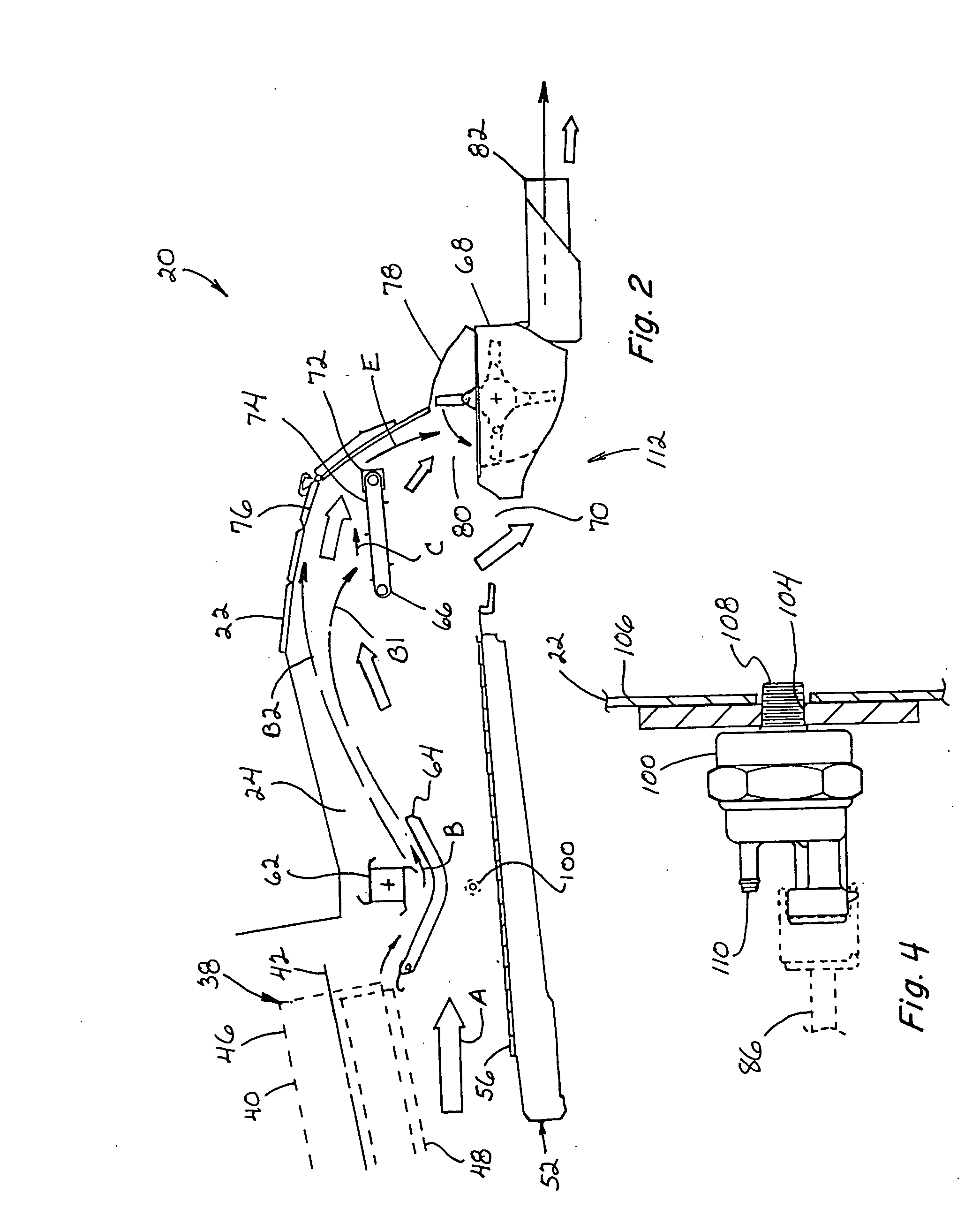
[0011] This location is advantageous, as it locates the air pressure sensor out of the actual crop residue flow, and away from an actual plugging condition. Instead, the invention utilizes detected changes or variations in air pressure conditions at the location remote from the actual plugging condition, to enable determining the presence of conditions indicative of the onset of plugging and / or actual plugging, such that the detector, here, an air pressure sensor, is not subjected to adverse conditions of plugging, such as, but not limited to, being clogged or plugged with crop material, dust, or the like. Here, it should be recognized and understood also that pressure conditions at the location of the sensor can be affected by changing parameters, which can include ambient air conditions and moisture content and consistency of the crop residue, as well as different discharge apparatus set ups, for instance, a set up for directing crop residue into a chopper for chopping thereby; a set up for just spreading the crop residue; a set up for windrowing; and / or a set up for mixing chaff with the crop residue, and aspects of the system of the invention can be adapted for factoring such variables when determining the existence or non-existence of a plugging condition. Additionally, the criticality of plugging under a particular discharge set up can be a factor. For instance, if windrowing, the clearing of a plug may not be as difficult and / or time consuming, compared to if the inlet of a chopper is plugged, and the system can be adjusted or calibrated to output a warning or make adjustments accordingly. For instance, when windrowing, a warning of a plugging condition may be outputted at a later time compared to if chopping crop residue. According to another preferred aspect of the invention, the combine includes a pan or concave disposed in the space beneath the beater and above the air flow channel, for guiding the crop residue flow propelled by the beater, and the air pressure sensor is preferably disposed below the concave. The cleaning system can further include a generally flat, horizontal sieve disposed below the air flow channel, and the air pressure sensor is preferably disposed above the sieve. This location, below the concave and above the cleaning system sieve, places the sensor in a flow channel for air from a fan of the cleaning system, and it has been found that air pressure conditions at this location are good indicators of the onset and existence of plugging conditions more rearwardly in the discharge area of the combine.

Problems solved by technology

Generally, straw walkers, which involve crank mechanisms for conveying the crop residue 2b rearwardly through a combine, are relatively slow in operation and thus have a limited material handling capability or rate.
The crank mechanisms add complexity and vibration.
Although discharge systems such as briefly discussed above have also improved, the harvesting and threshing systems of modern combines can at times produce volumes of crop residue material that can exceed the capacity of the discharge systems, leading to plugging thereof and packing of crop residue thereagainst and over the cleaning system, which can require substantial down time and effort to remove.
In some instances, the only warning of plugging is when an operator notices that crop residue is no longer being discharged or is being discharged at a rate which appears to be too low or the pattern of discharge is incorrect.
As an additional problem, if crop residue falls short of the rear of the combine, blockages and interference with and reduction in the effectiveness in the operation of the chaff handling system of the combine can occur, thereby also resulting in combine down time, decreases in harvesting productivity, and increases in operator and owner dissatisfaction and component failure.

Method used


Image

  • System and method for detecting a condition indicative of plugging of a discharge path of an agricultural combine
  • System and method for detecting a condition indicative of plugging of a discharge path of an agricultural combine
  • System and method for detecting a condition indicative of plugging of a discharge path of an agricultural combine

Examples


Embodiment Construction

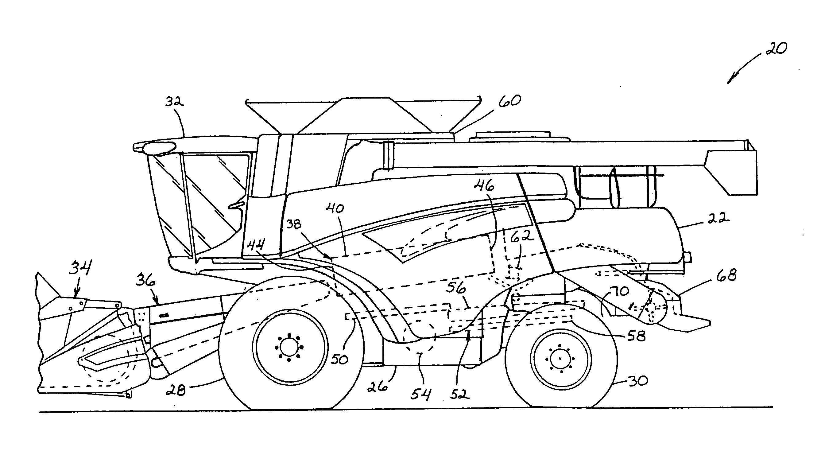
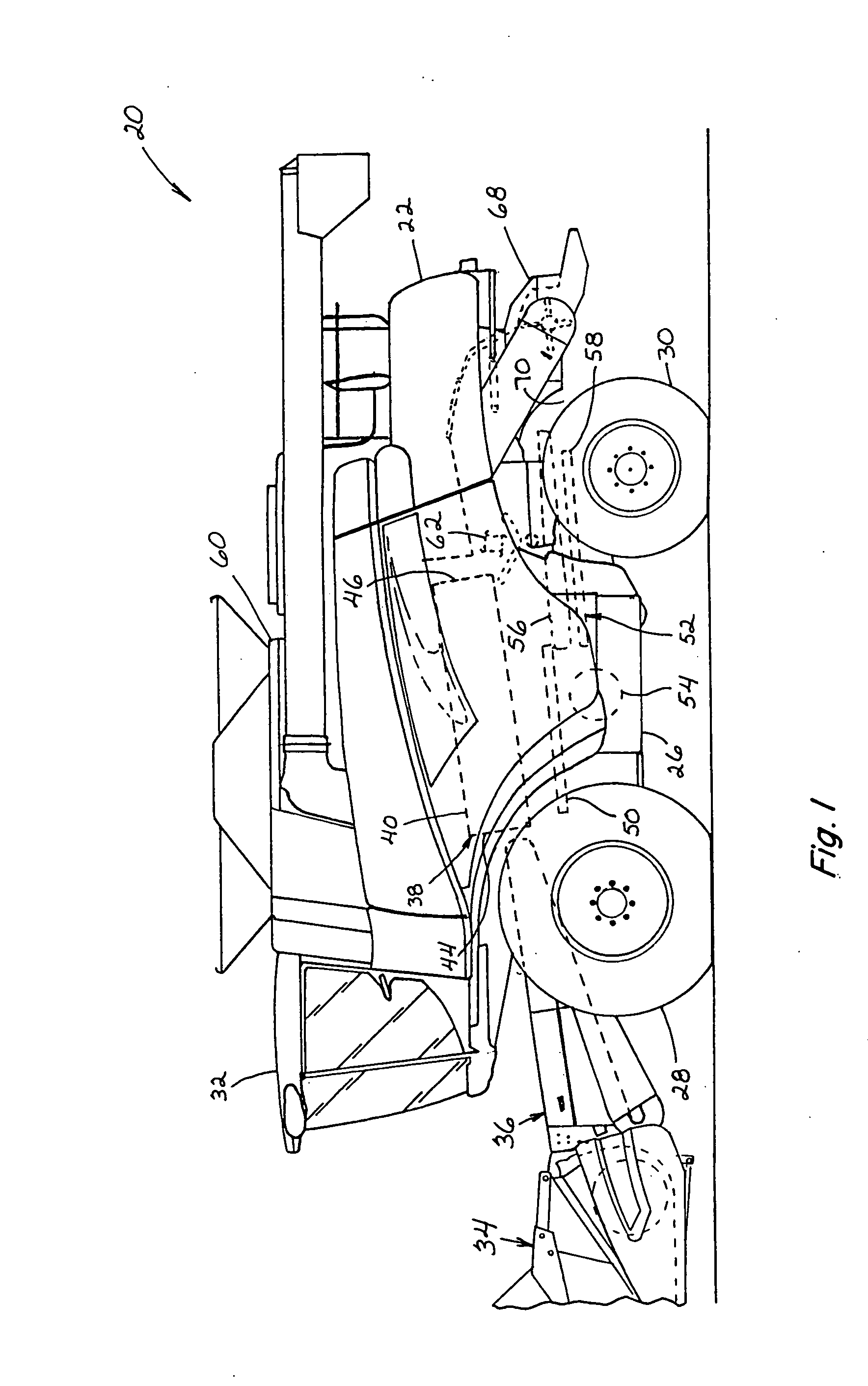
[0022] Referring to the drawings, FIGS. 1 and 2 show a self-propelled rotary combine 20 that includes a housing or body 22 defining an internal open area or space 24. While a conventional rotary combine is shown, it is anticipated that the present invention could be used with any type of combine, such as a conventional combine having a threshing cylinder and separation beaters (not shown) or a hybrid combine having a threshing cylinder and rotors (not shown). However, for ease of explanation, the present invention will be discussed hereinafter in conjunction with a self-propelled rotary combine 20 as illustrated by FIGS. 1 and 2.

[0023] The body 22 of the combine 20, which can include a supporting frame 26, is supported on front drive wheels 28 and steerable rear wheels 30. The combine 20 is powered by an engine (not shown) and controlled from an operator's station 32.

[0024] A crop harvesting apparatus, otherwise referred to as a header 34, and an infeed mechanism 36 are attached a...


PUM


Abstract

A system and method for detecting a condition indicative of onset of plugging or actual plugging of a discharge of an agricultural combine, utilizing a pressure sensor disposed at a location within the combine spaced from the discharge and operable for sensing an air pressure condition relating to a flow indicative of a reduced crop residue flow condition toward or in the discharge.

Description

TECHNICAL FIELD [0001] The present invention relates generally to a system and method for detecting a condition indicative of plugging of a path for discharging crop residue from an agricultural combine, and more particularly, for detecting a condition indicative of the onset of plugging, to allow avoiding occurrence of actual plugging and the requirement of removing the plug. BACKGROUND ART [0002] Agricultural combines are well known in the art for harvesting and threshing various agricultural crops, including for example, wheat, soybeans, corn, etc. Usually, agricultural combines include a harvesting apparatus, an infeed mechanism, a separating apparatus and a cleaning apparatus. In operation, the harvesting apparatus reaps the crop, which is planted in the ground. After reaping, the infeed mechanism feeds the crop to the separating apparatus. [0003] Typically, the separating apparatus in a rotary combine includes at least one rotor, which can extend axially (front to rear) or tra...

Claims


Application Information

Patent Timeline
IPC IPC(8): A01F12/40
CPCA01D41/1276
Inventor SMITH, DWAYNE B.
Owner BLUE LEAF I P
Learn More