Multi part non metal implant

a multi-part, non-metal technology, applied in the field of implants, can solve the problems of inconvenient bone insertion of ceramic implant components, high cost of industrial scale manufacturing, and high machining time of internal structures within sintered ceramic bodies,

Inactive Publication Date: 2006-11-02
FRIADENT
View PDF49 Cites 59 Cited by
  • Summary
  • Abstract
  • Description
  • Claims
  • Application Information

AI Technical Summary

Benefits of technology

[0016] It is therefore an object of the invention to provide an improved dental implant comprising a dental implant component for inserting into the jawbone of a patient which provides flexibility for a dentist preparing dental non-metal restoration.
[0018] This and other objects are achieved by a two phase implant comprising a fixture intended for insertion into a bone, and at least one further abutment component for providing a base for a prosthetic superstructure, and a connecting element for mechanically securing the abutment to the fixture, wherein the fixture comprises an external thread or other protrusions for improving engagement between the fixture and the bone, wherein the connecting element detachably interconnects the fixture and the abutment, and wherein at least the fixture and the abutment are made of non-metal material.
[0021] For easy and less costly manufacture even of a single implant, at least the cavity and the interlocking means are manufactured by machining a pre-sintered ceramic body, in particular if the dimensions of the pre-sintered ceramic body during machining are a reproduction of the desired end product at an enlarged scale.
[0023] To enhance healing-in of the fixture it is suitable that at least the fixture has a surface roughened by an abrasive mechanical, physical or chemical surface treatment, particularly, if the surface treatment comprises laser treatment and plasma etching.

Problems solved by technology

The sintered ceramic body can be treated by machining and grinding as commonly known, with the also known disadvantages of these methods, that is heavy tool abrasion and costly machining time.
However, machining of internal structure within a sintered ceramic body, like an internal thread is extremely costly and and economically unacceptable for industrial scale manufacturing.
WO 03 / 045268 A1 particularly describes that ceramic implant components for insertion into a bone have been found unsuitable, and particularly, that it seems impossible to provide zirconium oxide ceramic fixtures as a replacement for known metal two part implant components.
Although these connections providing the advantage that the adjustment work in the mouth of the patient is much less than that of a cone fitting, these have the disadvantage that the rotational position is defined in steps and prevents rotation of position, as the component inserted into the bone and becoming firmly anchored there after the healing-in phase predetermines the final position of the support projecting into the mouth to which a dental prosthesis is applied.
A further problem with those positive fit rotational locks is the necessity of producing such connection elements with tolerances to ensure that the parts of the connection can be mounted together at all, thus, in practice makes it difficult, if not impossible, to provide a connection being free from play under the pulsating stress caused by the masticatory load applied with large forces and at a high cyclic rate.
This may cause that a small amount of play present in the assembled structure at the beginning will become larger as the functional period increases causing small gaps between the components causing a risk of an intrusion of bacteria into the gap and / or mechanical disintegration of the assembly.
An important issue with respect to dental implants has been described as the mechanical connection between the implant and the jawbone.
Whilst a large implant provides the advantage that the forces can be transferred to the bone over a larger surface area and, thus, the mechanical stress is reduced, a large implant has the disadvantage that the remaining bone material may be reduced and incapable of receiving the forces transferred by the implant because of a stress overload of the bone material.
However, the methods described require high costs for preparing the molding tools, and relatively high production costs due to the many working steps required.

Method used


Image

  • Multi part non metal implant
  • Multi part non metal implant
  • Multi part non metal implant

Examples


Embodiment Construction

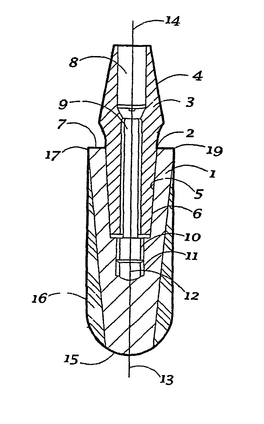
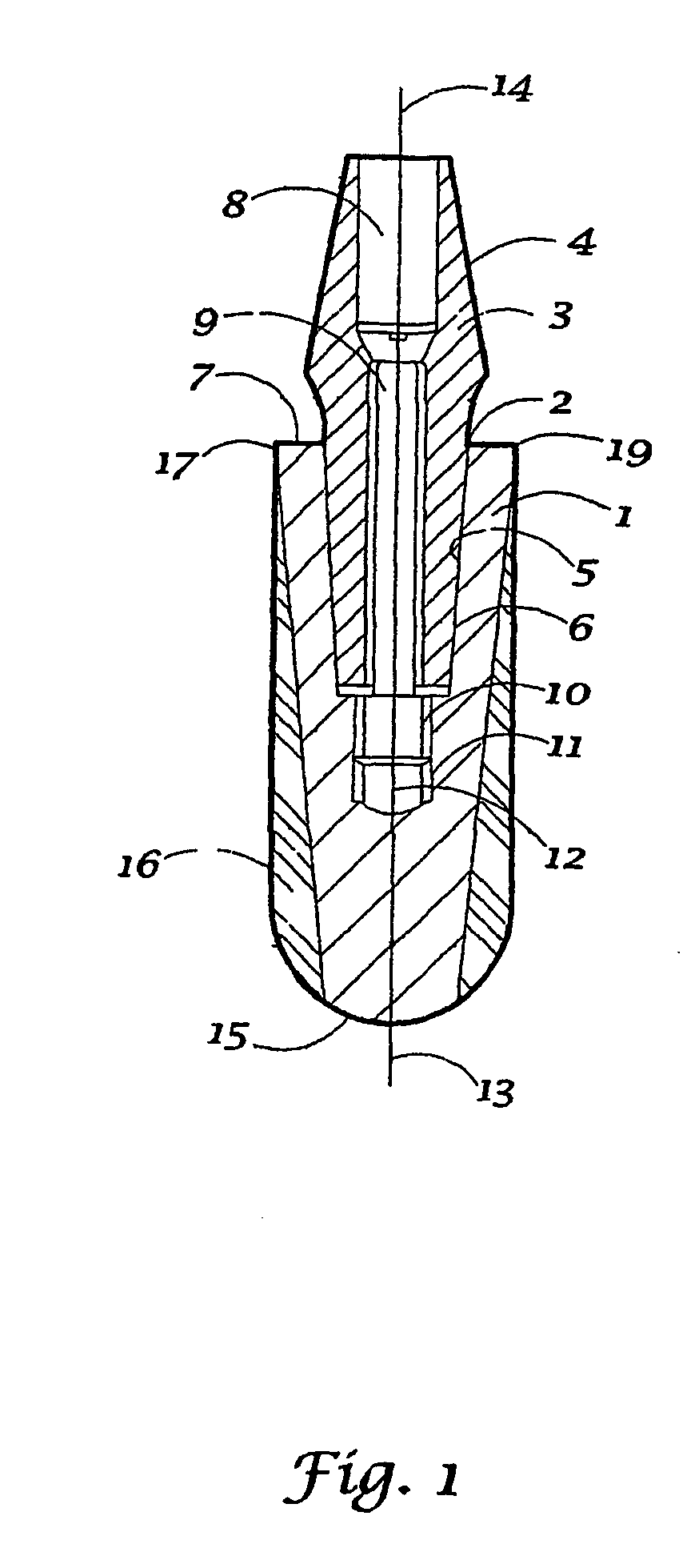
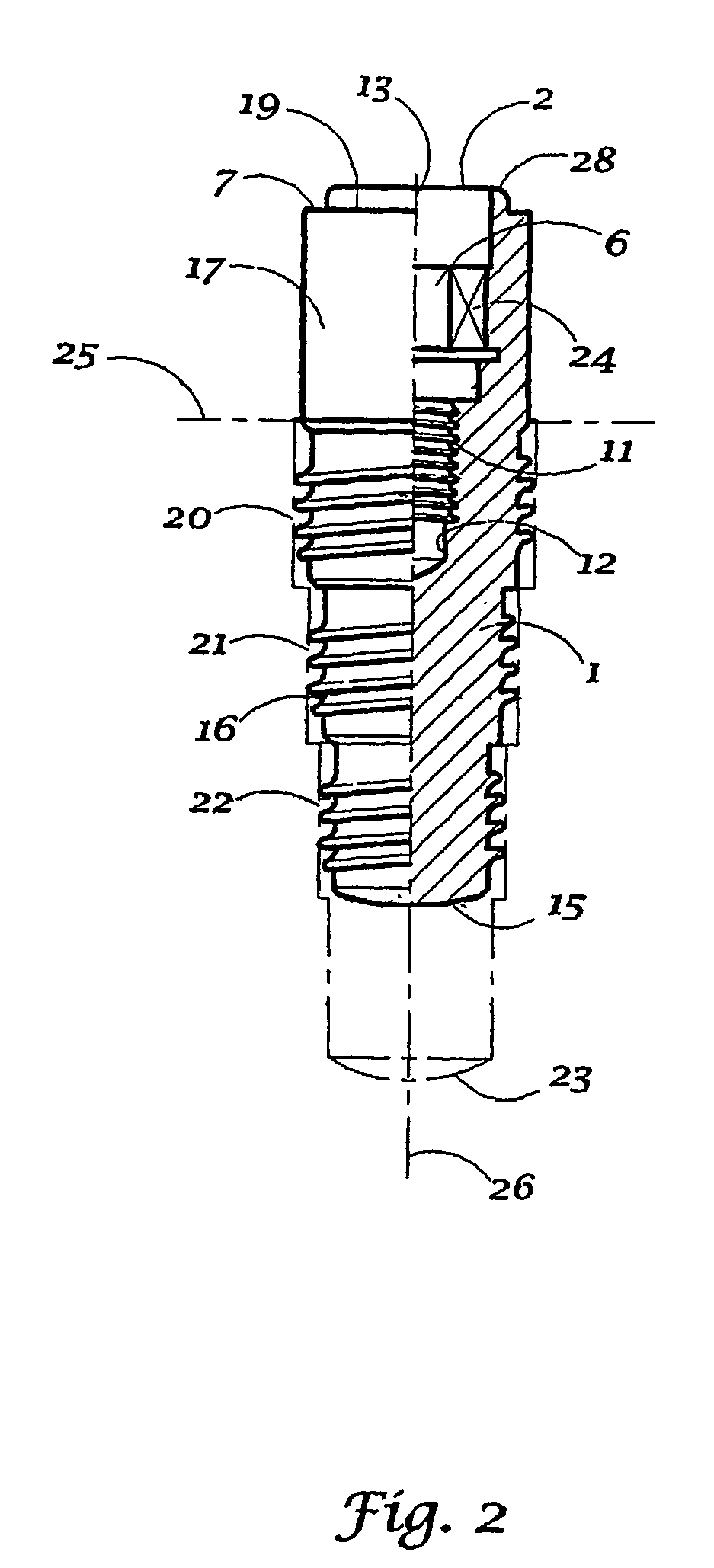
[0037] FIGS. 1 to 4 show various embodiments of dental implant components as examples of the invention. Although each of the embodiments has its own advantages in use common features will not be described in detail with each of the embodiments. Therefore, similar features in the different embodiments will be designated with the same reference numbers. Any description of these embodiments is for illustrative purpose and of exemplary nature only. Nothing described or not described in this regard should be construed as a limitation of what is claimed.

[0038] In FIG. 1 a two-phase, two component tooth implant is shown, which is capable of being steplessly positioned in its rotational orientation, including a first implant fixture component 1, having a central cavity opening 2, which fixture 1 is capable of being inserted into a jawbone, and a second implant abutment component 3 which may carry a dental prosthetic superstructure (not shown), like a crown or bridge. The second component 3...


PUM


Abstract

An implant is disclosed comprising a fixture component (1) intended for insertion into a bone, and at least one further abutment component (3) for providing a base for a prosthetic superstructure, and a connecting element (9) for mechanically securing the abutment (3) to the fixture (1), wherein the fixture (1) comprises an external thread (16) or other protrusions for improving engagement between the fixture (1) and the bone, wherein the connecting element (9) detachably interconnects the fixture (1) and the abutment (3), and wherein at least the fixture (1) and the abutment (3) are made of non-metal material, and method of making the same.

Description

INTRODUCTION AND BACKGROUND [0001] The present invention relates to an implant comprising a first fixture component intended for insertion into a bone, and at least one further abutment component for providing a base for a superstructure. [0002] A dental superstructure may comprise an individual tooth replacement or dental prosthesis. For intra-ossal tooth implants a distinction is made between so called single-phase and two-phase systems. Generally, a single-phase implantation is made in a single surgery step, often for early loading, and a two-phase implantation requires two surgery steps, the first for inserting an implant component into the bone, which is allowed to healing-in for a determined time, mostly tissue covered, and the second step for reopening the tissue, where applicable, and affixing further implant component for completing the desired functional capability of the implant. A preference is depending on the needs and corresponding medical treatment concept for an ind...

Claims


Application Information

Patent Timeline
IPC IPC(8): A61C8/00A61C13/00
CPCA61C8/0006A61C8/0012A61C8/0013A61C8/0022A61C8/0045A61C8/005A61C2008/0046A61C8/006A61C8/0068A61C8/0069A61C8/0071A61C13/0003A61C8/0054A61C8/00
Inventor WOLF, DIETRICH
Owner FRIADENT
Why Eureka
Try Eureka