Eureka AIR delivers breakthrough ideas for toughest innovation challenges, trusted by R&D personnel around the world.

Light-emitting material and organic electroluminescent device using the same

a technology of light-emitting materials and organic electroluminescent devices, which is applied in the direction of solid-state devices, discharge tubes/lamp details, natural mineral layered products, etc., can solve the problems of serious affect on the luminance efficiency and light color of the organic electroluminescent devices using pyrenes, and achieve the effect of reducing the effect of - stacking, improving the three-dimensional properties of light-emitting materials, and avoiding the effect of -

Active Publication Date: 2006-10-26
CHINA STAR OPTOELECTRONICS INT HK
View PDF3 Cites 11 Cited by
  • Summary
  • Abstract
  • Description
  • Claims
  • Application Information

AI Technical Summary

Benefits of technology

[0010] It is therefore an object of the present invention to provide a light-emitting material and an organic electroluminescent device using the same. The emissive layer including two pyrenes bonded together via different link rings can improve the three-dimensional properties of the light-emitting material. The limitations of the conventional design using pyrenes with substituting group to improve the three-dimensional properties of pyrenes can be avoided. Therefore, the present invention not only can decrease the effect of π-π stacking on the light color but also can avoid the decline of light color and the poor luminance efficiency in the conventional organic electroluminescent device using pyrenes with substituting groups. The light color and the luminance efficiency of the organic electroluminescent device using the light-emitting material of the present invention are much better than those of the conventional organic electroluminescent device including pyrenes with substituting groups. Moreover, the light-emitting material of the present invention has good thermal stability and luminance efficiency. The wavelength of the light emitted from the light-emitting material of the present invention inclines to that of blue light. As a result, the light-emitting material of the present invention is very suitable for blue light-emitting material or light-emitting material in another color.

Problems solved by technology

Because the host material in the excited state is unstable, the host material certainly returns to the ground state and transfer energy to the dopants.
As a result, the light color and the luminance efficiency of the organic electroluminescent device using pyrenes are affected seriously.
Although the three-dimensional properties of pyrenes become better due to having the substituents, the substituting groups beside pyrenes lower the light color and the luminance efficiency of the organic electroluminescent device using pyrenes with the substituting group.

Method used


Image

  • Light-emitting material and organic electroluminescent device using the same
  • Light-emitting material and organic electroluminescent device using the same
  • Light-emitting material and organic electroluminescent device using the same

Examples


first embodiment

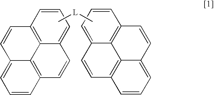
[0023] A light-emitting material is provided in the present embodiment of the invention. Two pyrenes are bonded together via a different link ring L to form the light-emitting material, for improving the three-dimensional properties of the pyrenes. This design is totally different from the conventional design using pyrenes doped with substituting groups to improve the three-dimensional properties of the pyrenes. The main chemical structure of the light-emitting material of the present embodiment of the invention represented by the formula [1]:

[0024] The chemical structure L defines as the structure of the link ring for bonding the two pyrenes. The chemical structure L includes the chemical structure A and the chemical structure B. The chemical structure L can be selected from the group consisting of the chemical structures AA, BB, AB, and the combination thereof. The chemical structures A and B are illustrated in detail as follows. As to the definition of the chemical structure A,...

third embodiment

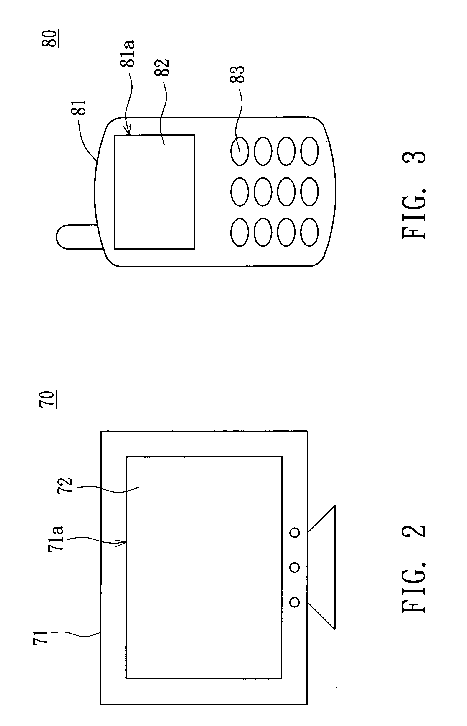
[0059] Referring to FIG. 3, a flat panel display apparatus according to the third embodiment using the organic electroluminescent device of the present invention is illustrated. A flat panel display apparatus can be a portable display apparatus 80, such as a mobile phone, a hand-held video game, a digital camera (DC), a digital video (DV), a digital displayer, a personal digital assistant (PDA), a notebook, or a table PC. In the present embodiment of the invention, the portable display apparatus 80 is a mobile phone for example.

[0060] In FIG. 3, the portable display apparatus 80 includes a housing 81, a display panel 82 and a set of press buttons 83. The display panel 82 at least includes the pre-mentioned organic electroluminescent device 10 and is disposed on the housing 81. Moreover, a display area of the display panel 82 is exposed to the surroundings through a front opening 81a of the housing 81. The set of press buttons 83 is disposed on a front surface of the housing 81 and ...


PUM

PropertyMeasurementUnit
weightsaaaaaaaaaa
weightsaaaaaaaaaa
fluorescentaaaaaaaaaa

Abstract

An organic electroluminescent device (OELD) is provided. The OELD includes a substrate, an anode, a cathode and an emissive layer. The anode and the cathode opposite to the anode are disposed over the substrate. The emissive layer is disposed between the anode and the cathode. The emissive layer includes a light-emitting material. The chemical structure of the light-emitting material represented by the formula [1]: The chemically structure L is selected from a group consisting of the chemical structures AA, BB, AB, and the combination thereof. The chemical structure A of the formula [2]: The chemical structure X is selected from the group 4A to 6A elements of the periodic table. The chemical structure B is aromatic hydrocarbons having n benzene, n is a integer of 1 to 8. The chemical structure B of the formula [3]:

Description

[0001] This application claims the benefit of Taiwan application Serial No. 94112789, filed Apr. 21, 2005, the subject matter of which is incorporated herein by reference. BACKGROUND OF THE INVENTION [0002] 1. Field of the Invention [0003] The present invention relates in general to a light-emitting material and an organic electroluminescent device using the same and, more particularly, to a light-emitting material including two pyrenes bonded together via different link rings and an organic electroluminescent device using the same. [0004] 2. Description of the Related Art [0005] A conventional organic electroluminescent device (OELD) is a multi-layer stacked structure including a substrate, an anode, a cathode, a hole injection layer, a hole transport layer, an electron transport layer, an electron injection layer and an emissive layer. The anode, the hole injection layer, the hole transport layer, the emissive layer, the electron transport layer, the electron injection layer and t...

Claims


Application Information

Patent Timeline
Patent Type & Authority Applications(United States)
IPC IPC(8): C09K11/06H01L51/54H05B33/14
CPCC09K11/06C09K2211/1011H05B33/14H01L51/0054H01L51/5012C09K2211/1029Y10S428/917H10K85/622H10K50/11
Inventor TAI, CHIA-LIANGYU, CHEN-PINGSU, YING-JU
Owner CHINA STAR OPTOELECTRONICS INT HK
Why Eureka
Eureka Blog
Learn More