Office machine

Inactive Publication Date: 2006-10-26
KYOCERA DOCUMENT SOLUTIONS INC
View PDF0 Cites 4 Cited by
  • Summary
  • Abstract
  • Description
  • Claims
  • Application Information

AI Technical Summary

Benefits of technology

[0010] With the above-described construction, the bearing unit is secured to a bottom plate forming a lower face of the housing body. Hence, the bearing unit can be secured easily, without requiring any special modification of the housing body. Further, the bottom plate defines an opening, through which the wheel is introduced to a position upwardly of the bottom plate to be supported to the bearing unit. Therefore, with the simple modification of defining an opening in the bottom plate, the supporting height of the housing body can be maintained low, even when a wheel with a large radius is supported to the bearing unit.
[0020] Further, since the securing is realized under the face contact condition described above, the bearing unit and the housing body tongue-like extension can be combined together or integrated to provide higher rigidity, so there will occur no significant lateral displacement between the bearing unit and the housing body tongue-like extension. Accordingly, it is possible to minimize a bending force which may be applied from the bearing unit to the side plate of the housing body. As a result, the posture of the office machine can be stabilized, and the durability of the office machine can be improved also.

Problems solved by technology

However, when wheels of greater radius advantageous for smooth transporting of the machine are employed, this results in corresponding increase in the supporting height of the housing body.
As a result, the installment space may increase and the maneuverability of the machine can be impaired.
On the other hand, this construction suffers the drawback of requiring a troublesome machining operation such as bending or reducing work to form the recessed faces in the lower face of the housing body.

Method used


Image

  • Office machine
  • Office machine
  • Office machine

Examples


Embodiment Construction

[0025] Preferred embodiments of the invention will be described in details with reference to the accompanying drawings.

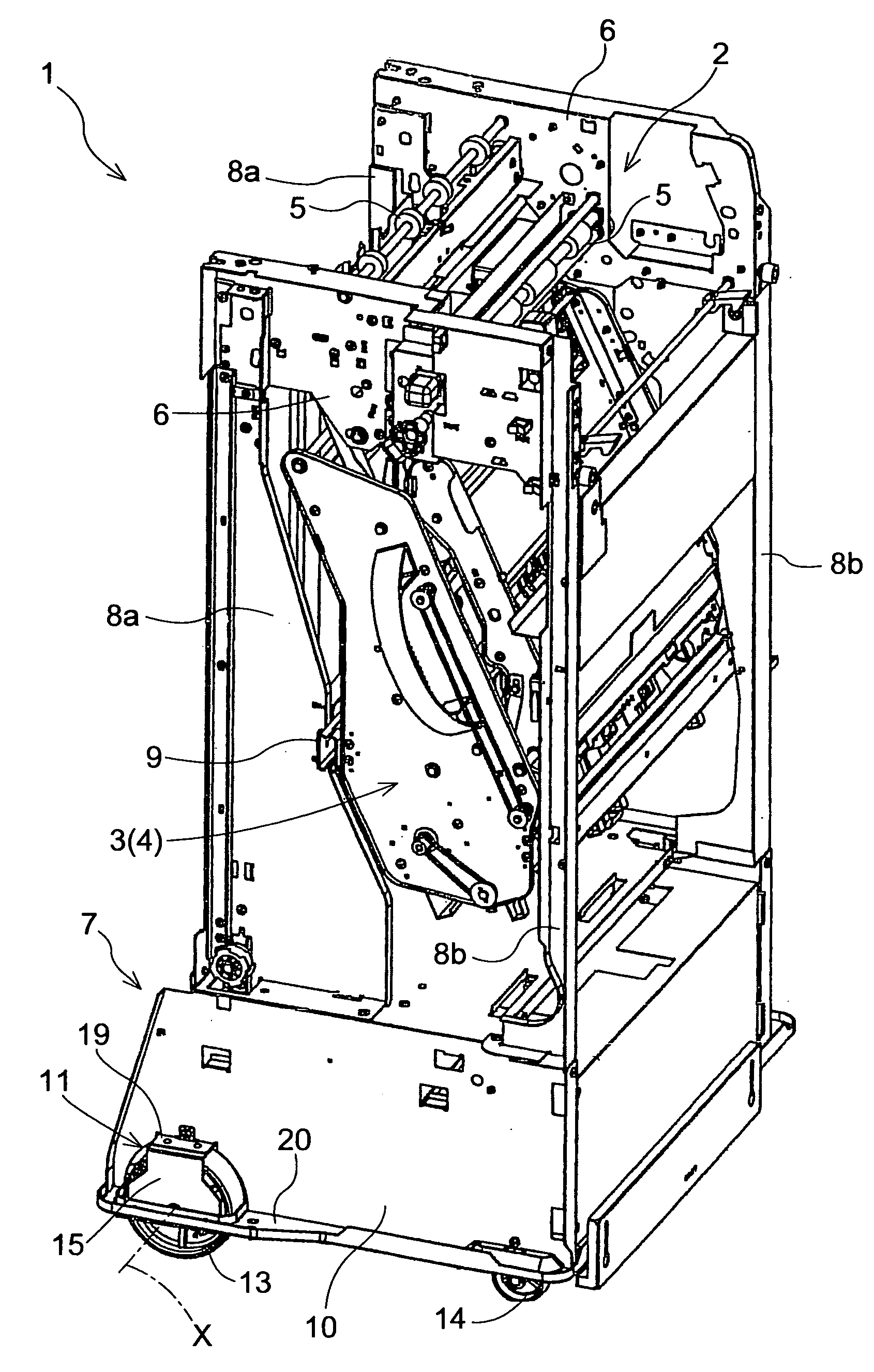
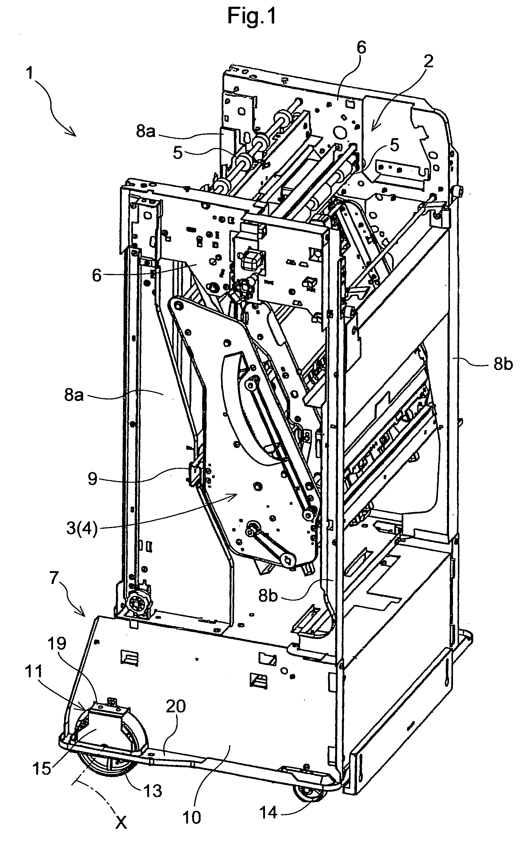
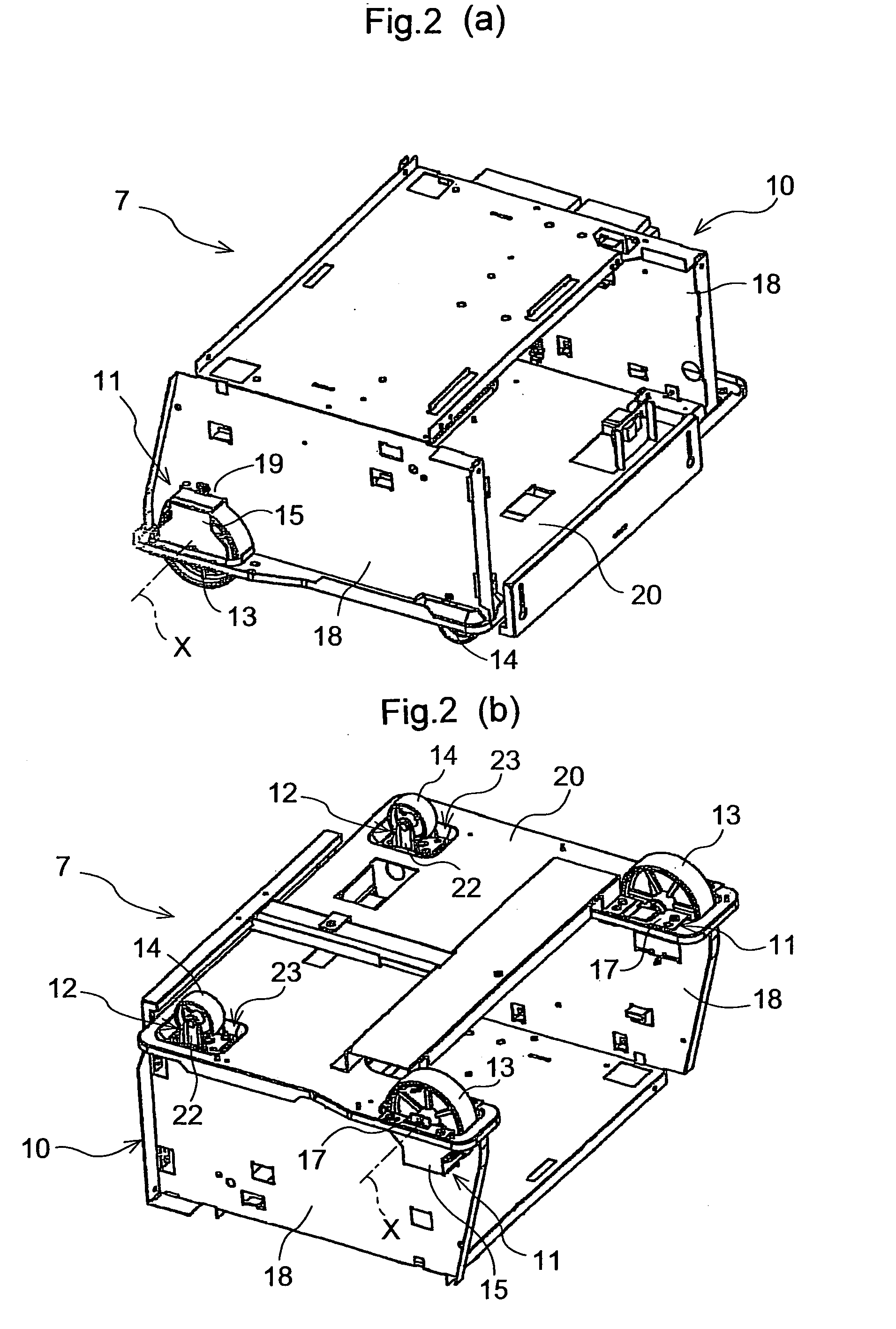
[0026]FIG. 1 shows a post processing unit 1 included in an image forming apparatus such as a photocopier, a printer or the like, as an example of an office machine relating to the invention. A paper carrying-in / out device 2 is capable of carrying in or carrying out an image-formed paper sheet discharged from a paper discharge outlet provided in an image forming section for copying an original document image on a paper sheet. As an example of the post processing unit, an intermediate tray 4 includes a stapling device 3 for stapling a plurality of image-formed paper sheets discharged from the paper carrying-in / out device 2 and a bottom support unit 7 is provided downwardly of the intermediate tray 4.

[0027] The paper carrying-in / out device 2 comprises a unit integrating e.g. a set of transport rollers 5 supported to a pair of right and left side plates 6 for carrying...


PUM


Abstract

An office machine includes a housing body, a bearing unit secured to the housing body and a caster wheel supported to the bearing unit to be rotatable about a horizontal axis. The bearing unit is secured to a bottom plate forming a lower face of the housing body. The bottom plate defines an opening, through which the caster wheel is introduced to a position upwardly of the bottom plate to be supported to the bearing unit.

Description

CROSS-REFERENCE TO RELATED APPLICATION [0001] The present application claims priority based on the Japanese Patent Application JP2005-127875 filed by the present applicant in Japan on Apr. 26, 20005. BACKGROUND OF THE INVENTION [0002] 1. Field of the Invention [0003] The present invention relates to an office machine such as an image forming apparatus including a copier, a printer, etc. or a movable rack, having caster wheels supported to bearing units secured to a housing body to be rotatable about horizontal axes. [0004] 2. Prior Art [0005] In the conventional office machines of the above-noted type, bearing units are secured to lower end faces of corner portions of the housing body extending along the vertical direction of the housing body and wheels (caster wheels) are rotatably supported to these bearing units (see e.g. Japanese Patent Application “Kokai” No. 9-304985 (referred to as “First Conventional Technique”, hereinafter)), or, upwardly recessed faces are formed in a bott...

Claims


Application Information

Patent Timeline
IPC IPC(8): B62B3/00
CPCB62B3/00F16M2200/08F16M11/22F16M11/42
Inventor TAGUCHI, TETSUYA
Owner KYOCERA DOCUMENT SOLUTIONS INC
Why Eureka
Try Eureka