Membrane packing dispenser

a technology of membrane reels and dispensers, which is applied in the field of membrane reels, can solve the problems of unable to fit membrane reels on sleeves, the membrane reel cannot be fixed on the sleeves, and the palm of a large palm can hardly get into the accommodating space for holding, etc., and achieves the effect of large accommodating spa

Active Publication Date: 2006-10-26
YU CHEN HSIU MAN
View PDF5 Cites 23 Cited by
  • Summary
  • Abstract
  • Description
  • Claims
  • Application Information

AI Technical Summary

Benefits of technology

[0006] The objective of the invention is to offer a membrane packing dispenser including a holding sleeve and a rotary shaft sleeve. The cylindrical portion of the rotary shaft sleeve is step-shaped and formed with a lower portion to be fitted with a membrane reel and an upper portion for receiving the cylindrical portion of the holding sleeve therein. The lower portion has its outer wall bored with plural slots respectively disposed therein with a tightening plate having its upper opposite sides respectively fixed with an engage projection. The lower portion of the rotary shaft sleeve has its interior secured with a circular projection having plural support ribs extending outward from the outer edge and respectively connected with the intermediate portion of the tightening plate. The engage projections on the tightening plate are positioned a little higher than the outer wall surface of the lower portion. Thus, the lower portion of the rotary shaft sleeve can be firmly engaged with the inner walls of, the opposite ends of a membrane reel by means of the engage projections of the tightening plates. The engage projections of the tightening plates can be diametric ally pressed to shift elastically; therefore, the rotary shaft sleeves of the membrane packing dispenser in the present invention can be applied for various membrane reels with a little difference in size. In addition, matching with the upper portion of the rotary shaft sleeve, which has a comparatively large diameter, the holding sleeve to be fitted in the upper portion of the rotary shaft sleeve can be formed with a comparatively large accommodating space for facilitating a user's hand to extend therein for holding.

Problems solved by technology

If the accommodating space 112 of the holding sleeve 11 is too narrow and small, a comparatively big palm can hardly get in the accommodating space for holding and may be hurt in case of operating forcefully.
Furthermore, although the diameters of the shaft tubes of common membrane reels are fixed in size, yet there may be still a little error between them; therefore, it is hard to guarantee that every membrane reel can be firmly fitted with the engaged ribs 122 of the sleeve body 121 of the rotary shaft sleeve 12, likely to render the membrane reel unable to be fitted on the sleeve body 121 of the rotary shaft sleeve 12 or impossible to be secured tightly due to excessive slackness.

Method used


Image

  • Membrane packing dispenser
  • Membrane packing dispenser
  • Membrane packing dispenser

Examples


Embodiment Construction

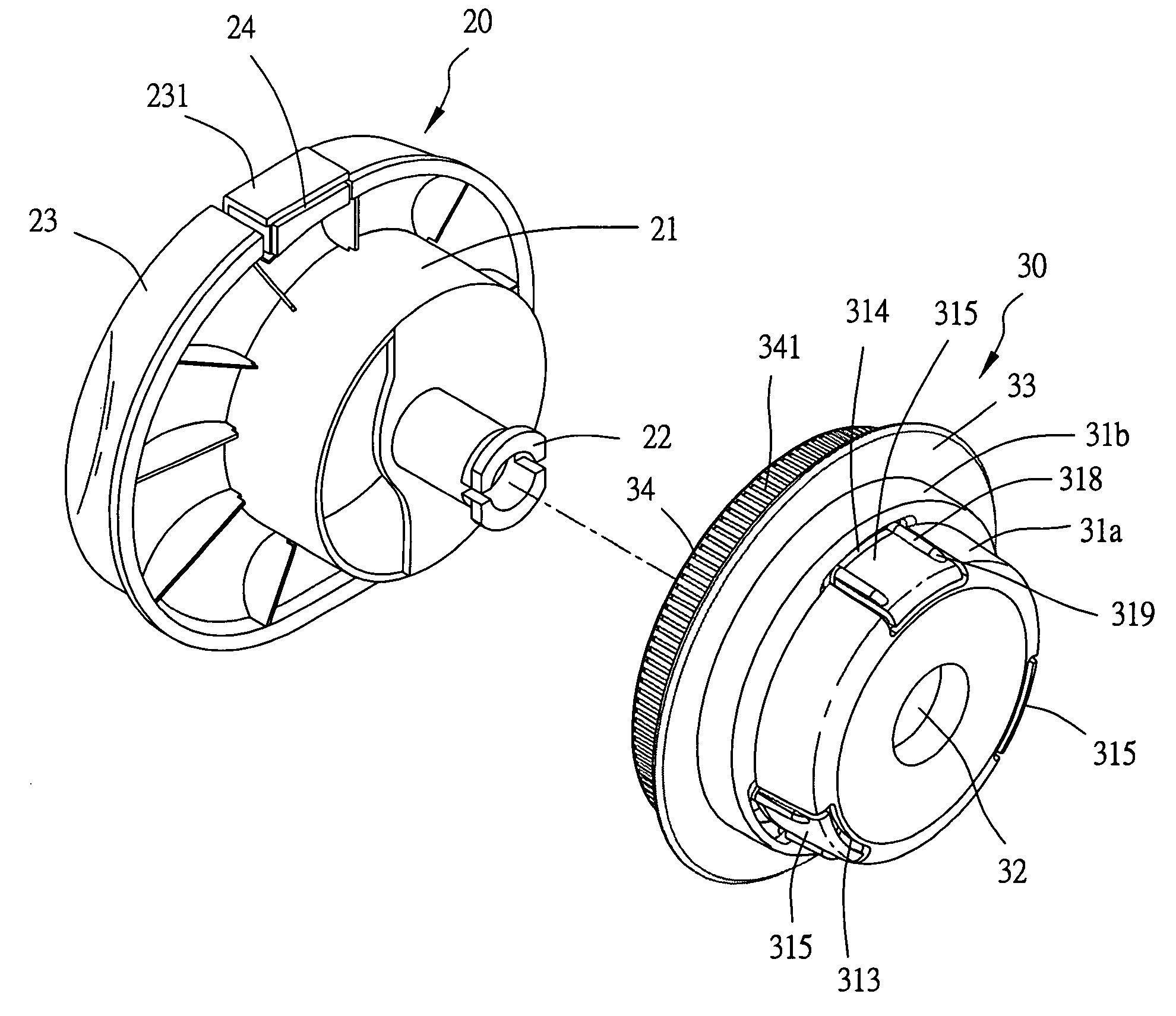
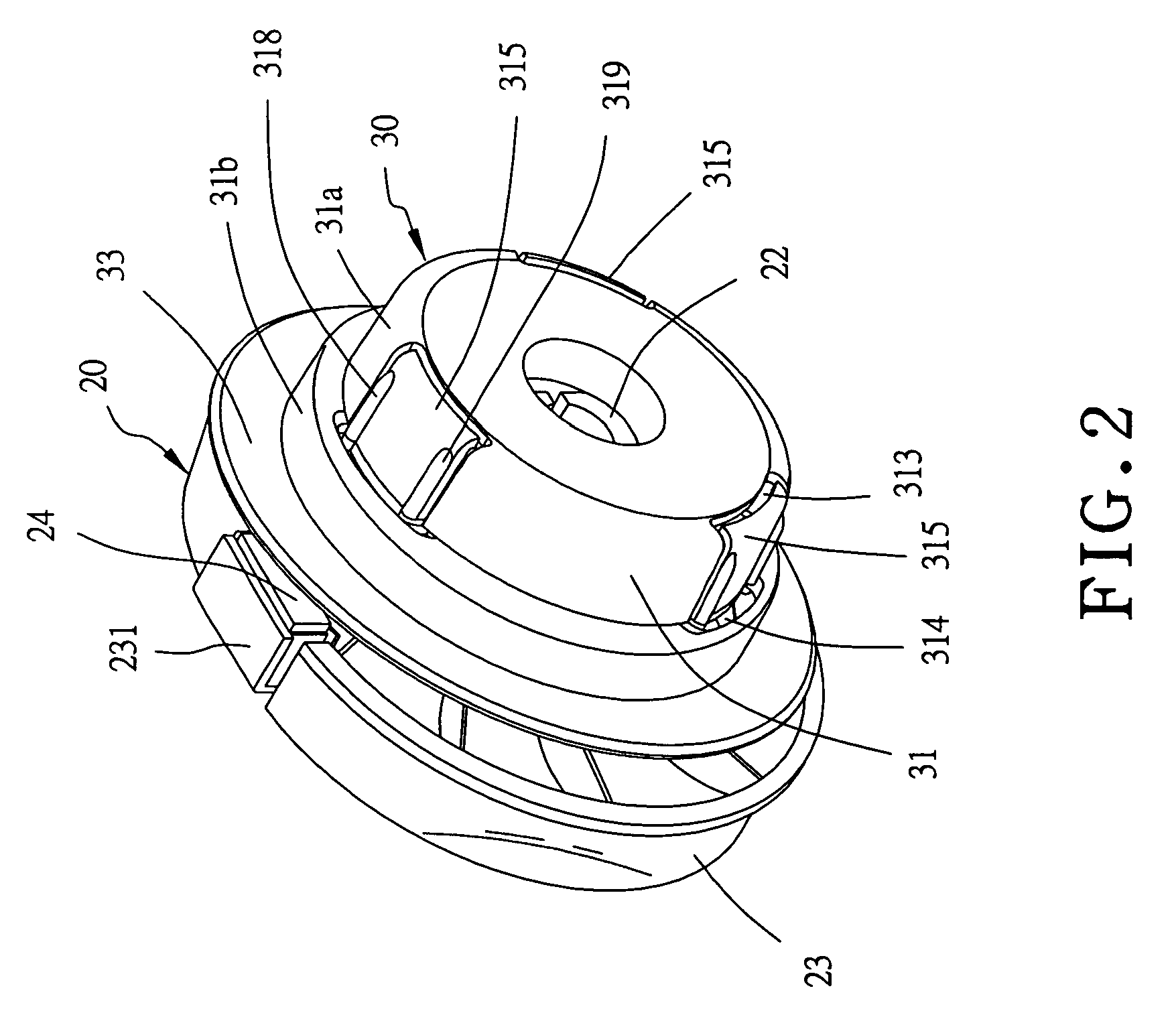
[0014] A preferred embodiment of a membrane packing dispenser in the present invention, as shown in FIGS. 2, 3 and 4, includes a holding sleeve 20 and a rotary shaft sleeve 30 combined together.

[0015] The rotary shaft sleeve 30 is formed with a cylindrical portion 31 for receiving and positioning the cylindrical portion 21 of the holding sleeve 20. The cylindrical portion 21 of the holding sleeve 20 has its lower end fixed with a projecting engage member 22 to be inserted and engaged in the shaft hole 32 in the lower end of the cylindrical body 31 of the rotary shaft sleeve 30 to enable the holding sleeve 20 and the rotary shaft sleeve 30 to rotate together for releasing of a membrane. The cylindrical portion 31 of the rotary shaft sleeve 30 has its outer side edge extending upward diametrically and forming a circular stopping wall 33 and an annular projecting wall 34 extending forward and having its outer circumferential surface formed with numerous slide-stopping lines 341. The c...


PUM


Abstract

A membrane packing dispenser includes a rotary shaft sleeve and a holding sleeve. The cylindrical portion of the rotary shaft sleeve is step-shaped and formed with a lower portion to be fitted with a membrane reel and an upper portion for receiving the cylindrical portion of the holding sleeve. The lower portion of the rotary shaft sleeve has its outer wall bored with plural slots respectively disposed therein with a tightening plate having its upper opposite sides respectively fixed with an engage projection. Thus, the lower portion of the rotary shaft sleeve can be firmly engaged with the end of a membrane reel by the engage projections of the tightening plates. The engage projections can be elastically adjusted to shift; therefore, the rotary shaft sleeves are applicable to various membrane reels with a little difference in size.

Description

BACKGROUND OF THE INVENTION [0001] 1. Field of the Invention [0002] This invention relates to a membrane packing dispenser, particularly to one able to enlarge a holding space for facilitating holding and applicable to various membrane reels with a little difference in size. [0003] 2. Description of the Prior Art [0004] A conventional membrane packing dispenser 10, as shown in FIG. 1, includes a holding sleeve 11 and a rotary shaft sleeve 12. The holding sleeve 11 is formed with a sleeve body 111 to be received in the sleeve body 121 of the rotary shaft sleeve 12 and has it s lower end firmly engaged with the lower end of the rotary shaft sleeve 12, enabling the rotary shaft sleeve 12 and the holding sleeve 11 to rotate relatively. The sleeve body 121 of the rotary shaft sleeve 12 has its outer wall surface provided with a plurality of elongate engage ribs 122 to be fixedly engaged with the inner walls of the shaft holes in the opposite ends of the central shaft tube of a membrane r...

Claims


Application Information

Patent Timeline
Patent Type & Authority Applications(United States)
IPC IPC(8): B65D85/02
CPCB65D85/02B65H16/04B65D85/671
Inventor CHEN, HSIU-MAN YU
Owner YU CHEN HSIU MAN
Why Eureka
Try Eureka