
Flanged interbody fusion device with hinge

a fusion device and hinge technology, applied in the field of spinal fixation systems and methods, can solve the problems of degenerative changes in bones, spine instability, pain and instability,

Active Publication Date: 2006-10-19
SPINAL ELEMENTS INC
View PDF100 Cites 94 Cited by
  • Summary
  • Abstract
  • Description
  • Claims
  • Application Information

AI Technical Summary

Benefits of technology

[0013] In one embodiment of the invention, an orthopedic implant assembly is provided, comprising a stabilizing element having a trailing surface, a leading surface and at least one lumen, the lumen having a first opening at the trailing surface, a second opening at the leading surface that is smaller than the first opening, and a passageway extending from the first opening to the second opening, a securing element having an elongated body, a head at one end of the body and integral therewith, and a lumen insert member defining a portion of the passageway, having an inner diameter and an outer diameter, and adapted to substantially reduce any force exerted between the stabilizing element and the securing element, wherein the diameter of the head of the securing element is greater than the lesser diameter between the second opening of the lumen and the inner diameter of the insert. The orthopedic implant may further comprise an interbody element integral with the leading surface of the stabilizing element and / or a locking assembly for resisting movement of securing element in at least one direction.
[0020] In another embodiment, an orthopedic implant assembly is provided, comprising a stabilizing element having a trailing surface, a leading surface and at least one lumen, the lumen having a first opening at the trailing surface, a second opening at the leading surface that may be smaller than the first opening, and a passageway extending from the first opening to the second opening, a securing element having an elongated body, a head at one end of the body and integral therewith, and a lumen insert member within a portion of the passageway, the lumen insert member comprising an inner diameter and an outer diameter, and adapted to substantially reduce any force exerted between the stabilizing element and the securing element, wherein the diameter of the head of the securing element may be greater than the lesser diameter between the second opening of the lumen and the inner diameter of the insert. The orthopedic implant assembly may further comprise an interbody element integral with the leading surface of the stabilizing element. The orthopedic implant assembly may further comprise a locking assembly for resisting movement of securing element in at least one direction.
[0038] In another embodiment, an orthopedic implant assembly is provided, comprising a stabilizing element having a trailing surface, a leading surface and at least one lumen, the lumen having a first opening at the trailing surface, a second opening at the leading surface that may be smaller than the first opening, and a passageway extending from the first opening to the second opening, a securing element having an elongated body, a head at one end of the body and integral therewith, and a lumen insert member within a portion of the passageway, the lumen insert member having an inner diameter and an outer diameter, and adapted to substantially reduce any force exerted between the stabilizing element and the securing element, wherein the diameter of the head of the securing element may be greater than the lesser diameter between the second opening of the lumen and the inner diameter of the insert. The orthopedic implant assembly may further comprise an interbody element integral with the leading surface of the stabilizing element. The orthopedic implant assembly may further comprise a locking assembly for resisting movement of securing element in at least one direction.

Problems solved by technology

Advancing age, as well as injury, can lead to degenerative changes in the bones, discs, joints and ligaments of the spine, producing pain and instability.
Spine instability may result from causes such as fracture, scoliosis and spondylolisthesis, where one or more vertebrae move in a forward direction relative to the other vertebrae.
Early fixation devices tended to be applicable only to long bone injuries with only limited uses for lower lumbar spinal injuries and disorders.

Method used


Image

  • Flanged interbody fusion device with hinge
  • Flanged interbody fusion device with hinge
  • Flanged interbody fusion device with hinge

Examples


Embodiment Construction

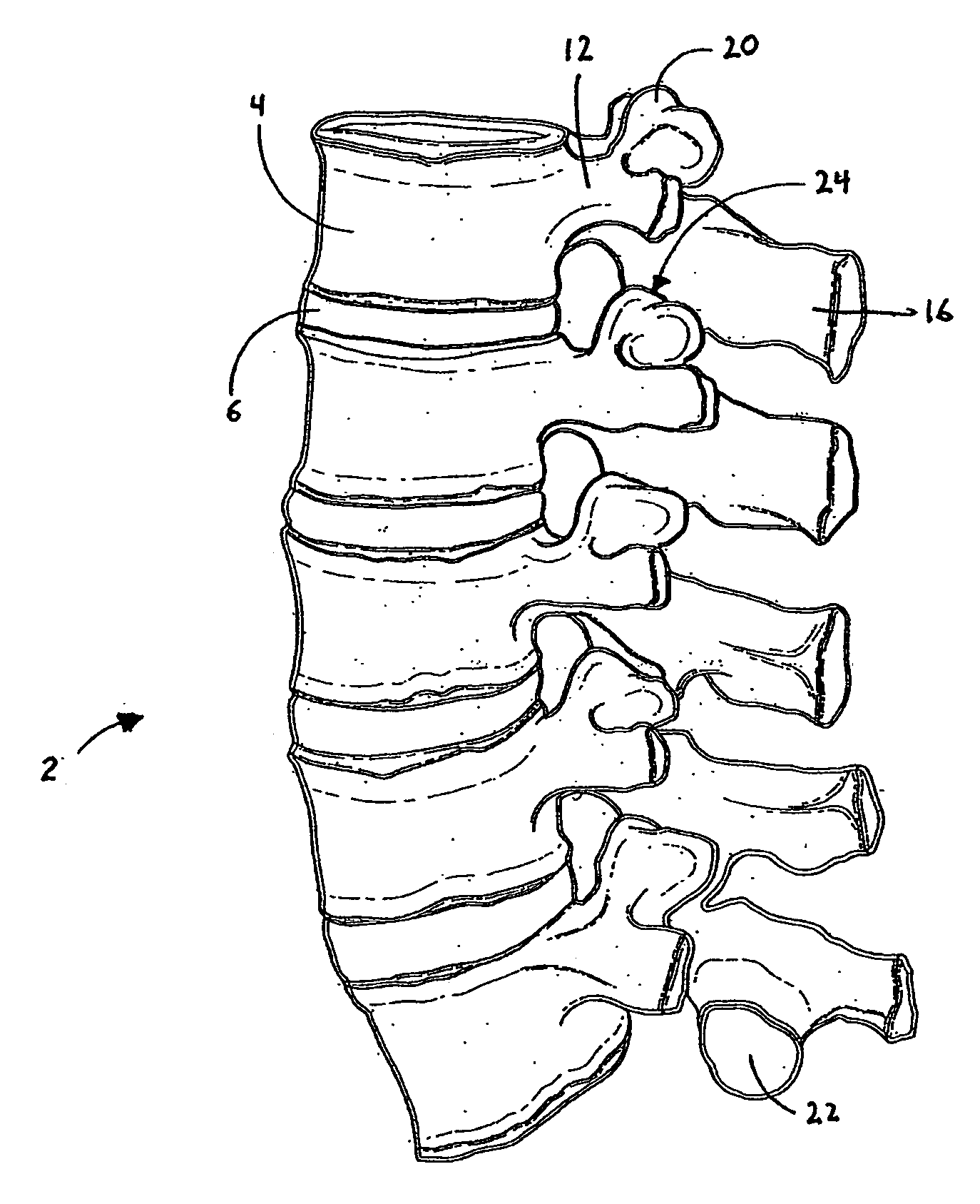
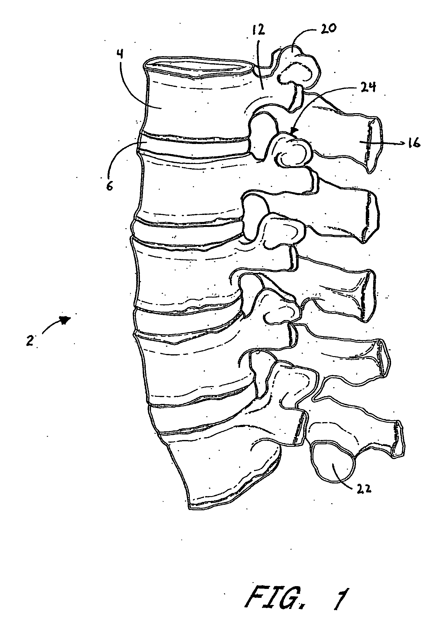
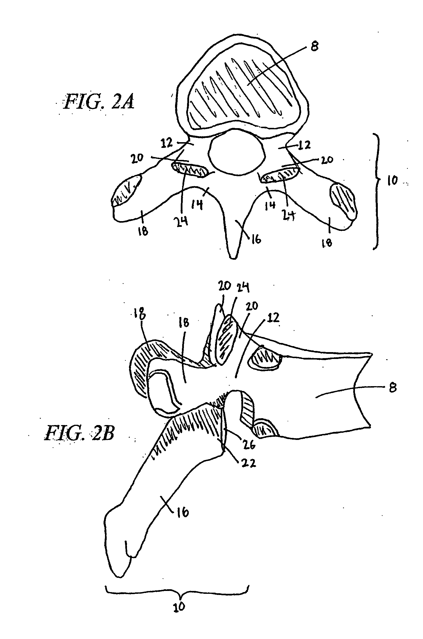
[0094] Advancing age, as well as injury, can lead to degeneration in the bones, discs, joints, and ligaments of the spine producing pain from nerve root compression. Under certain circumstances, alleviation of pain can be provided by performing a spinal fusion. Spinal fusion is a procedure that involves joining two or more adjacent vertebrae so that they no longer are able to move relative to each other.

[0095] In existing spinal fusion implants there have also been problems with loosening and backing out of screws into the patient's throat area. Backout is the exhibited tendency of bone screws, which affix the bone plate to the bone(s), to loosen with respect to both the plate and bone, resulting in poor fixation, fusion and ultimately, healing. Essentially, this loosening of the bone screw causes the screw to work itself out of the bone into which it is implanted. This results in the bone plate being poorly fixed in place thus becoming devoid of its fixation capabilities. Usually,...


PUM

PropertyMeasurementUnit
heightaaaaaaaaaa
heightaaaaaaaaaa
heightaaaaaaaaaa

Abstract

Methods and devices are disclosed for treating the vertebral column. An integrated fixation plate and spacer having a retaining structure within the screw holes of the fixation plate to resist backout of screws attaching the fixation plate to the bone is provided. A movable joint may be provided between the fixation plate and spacer. In some embodiments, a screw hole insert is also provided to resist shear forces acting between the screw and fixation plate. In some embodiments, an integrated fixation plate and spacer system is provided, comprising two or more integrated fixation plate and spacer implants, wherein the fixation plates of each implant has a complementary configuration to allow attachment of the implants at adjacent intervertebral spaces. Alternative fixation systems are also contemplated.

Description

CROSS-REFERENCE TO RELATED APPLICATIONS [0001] The present application claims priority under 35 U.S.C. §119(e) to U.S. Provisional Application No. 60 / 662,747 filed on Mar. 17, 2005 and U.S. Provisional Application No. 60 / 708,918 filed on Aug. 17, 2005, the disclosures of which are incorporated by reference herein in their entirety.BACKGROUND OF THE INVENTION [0002] 1. Field of the Invention [0003] This invention relates generally to systems and methods for performing spinal fixation. The invention comprises one or more vertebral spacers that feature an attachment system that resists backing out of the screws used to attach the spacers to the vertebrae. The invention may be configured so that multiple adjacent spacers may be used along the vertebral column. [0004] 2. Description of the Related Art [0005] Advancing age, as well as injury, can lead to degenerative changes in the bones, discs, joints and ligaments of the spine, producing pain and instability. Under certain circumstances...

Claims


Application Information

Patent Timeline
Patent Type & Authority Applications(United States)
IPC IPC(8): A61F2/44
CPCA61B17/7059A61F2310/00179A61B17/8047A61B2017/8655A61F2/447A61F2002/2817A61F2002/2835A61F2002/30062A61F2002/30131A61F2002/30166A61F2002/30378A61F2002/30462A61F2002/30471A61F2002/30484A61F2002/30495A61F2002/30505A61F2002/30514A61F2002/30517A61F2002/30578A61F2002/30677A61F2002/30772A61F2002/30794A61F2002/30904A61F2002/3092A61F2002/449A61F2210/0004A61F2220/0025A61F2220/0033A61F2220/0075A61F2220/0091A61F2230/0013A61F2230/0028A61F2310/00011A61B17/88A61F2/4455A61F2/46A61F2002/4415A61B17/8042A61F2002/3079A61B17/86
Inventor BLAIN, JASON
Owner SPINAL ELEMENTS INC
Learn More