
Image processing method, profile creation method, and image processing apparatus

a profile creation and image processing technology, applied in the field of image processing methods, profile creation methods, image processing apparatuses, can solve the problems of ineffective use of the the inability to include the full and the inability to use the entire color reproduction range of the output device. to achieve good color reproduction and prevent inconvenien

Inactive Publication Date: 2006-10-19
CANON KK
View PDF15 Cites 23 Cited by
  • Summary
  • Abstract
  • Description
  • Claims
  • Application Information

AI Technical Summary

Benefits of technology

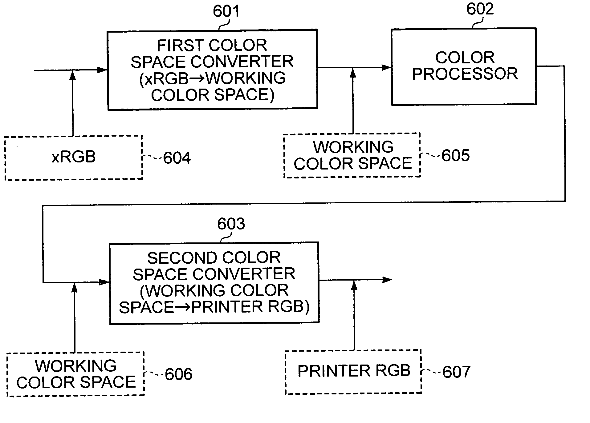
The present invention provides an image processing method, program, and image processing apparatus that can prevent color reproduction issues caused by the shape of the working color space involved in gamut mapping. This allows for good color reproduction to be achieved. The method involves performing gamut mapping on image data in a first color reproduction range to convert it into image data in a second color reproduction range. The shape of the first color reproduction range is determined based on the shape of the second color reproduction range. This results in improved color reproduction accuracy and efficiency.

Problems solved by technology

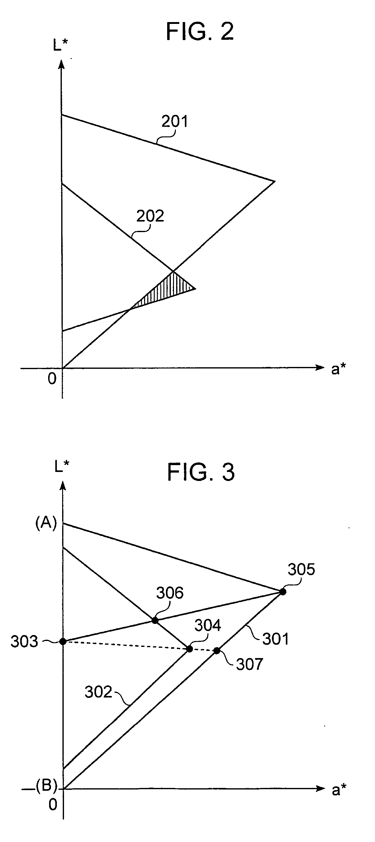
In gamut mapping, since the shape of a known working color space is changed basically only by mapping, such as compression, known gamut mapping can cause some problems described below.
First, the device-independent working color space discussed in the above-described documents cannot include the output device's full color reproduction range mapped through gamut mapping.
This leads to a problem in that colors reproducible by the output device cannot be effectively used.
The result is that full use of the entire color reproduction range of the output device cannot be made.
Another problem caused by gamut mapping is the reversal of color saturation and lightness. FIG. 3 illustrates this problem and shows the relationship between a working color space 301 and a color reproduction range 302 of an inkjet printer expressed in the CIE-L*a*b* color system.
However, this method involves complex and cumbersome processing for identifying the maximum saturation point in the printer's color reproduction range 302, and thus cannot be simply adopted.
Therefore, there are some cases where a color match between a specific color in the working color space and a specific color in the color reproduction range of the output device cannot be ensured by gamut mapping, and thus accurate color reproduction cannot be achieved.
Another conventional problem is associated with the conversion of nonexistent color information.
This results in the conversion of colors including unnecessary colors, and can cause a relative decrease in the accuracy of the LUT.

Method used


Image

  • Image processing method, profile creation method, and image processing apparatus
  • Image processing method, profile creation method, and image processing apparatus
  • Image processing method, profile creation method, and image processing apparatus

Examples


first embodiment

[0075]FIG. 9 is a flowchart showing an exemplary process of defining a working color space according to the first embodiment of the present invention.

[0076] Referring to FIG. 9, in step S901, the coordinates of the three primary colors, red, green, and blue, are defined in an (x,y)-type chromaticity diagram for the XYZ color system such that the color reproduction range of the printer 404, which is an output device, is included.

[0077]FIG. 10 is an exemplary (x,y)-type chromaticity diagram showing a color reproduction range 1002 of the printer 404 and a spectrum locus 1001 marking the boundary of a visible region. The area inside the horseshoe spectrum locus 1001 represents the visible region. In FIG. 10, a smooth dashed line 1003 marks the outer boundary of the color reproduction range 1002 of the printer 404 with a regression curve, such as a spline curve. Three points lying on the dashed line 1003 and satisfying the following conditions (1) to (3) are identified and connected by...

second embodiment

[0093] In the second embodiment, the working color space is defined so as to prevent gamut mapping from causing the reversal of color saturation and lightness, as well as to include the full color reproduction range of the printer as described in the first embodiment. Specifically, the position of each primary color in the working color space is moved so as to adjust the shape of the working color space to the shape of the color reproduction range of the printer, thus determining the shape of the working color space.

[0094]FIG. 13 is a flowchart showing an exemplary process of defining a working color space according to the present embodiment.

[0095] Steps S1301 to S1303 in FIG. 13 will not be described here, as they are substantially the same as those described in the first embodiment (Steps S902 to S903 shown in FIG. 9).

[0096] In step S1304, a determination is made as to whether the shape of the reference working color space WO determined in step S1303 is to be changed or adjuste...


PUM


Abstract

Three primary color points are defined to determine a working color space such that the working color space includes all colors in the color reproduction range of a printer. In addition, the luminance of a white point and a standard light source is defined. A transformation matrix is determined on the basis of these points. The transformation matrix associates an RGB working color space with a color space in the XYZ color system to define the RGB working color space. Thus, when compression gamut mapping is performed on the working color space, colors in the working color space can be mapped to any colors in the color reproduction range of a printer, without dropping any colors reproducible by the printer.

Description

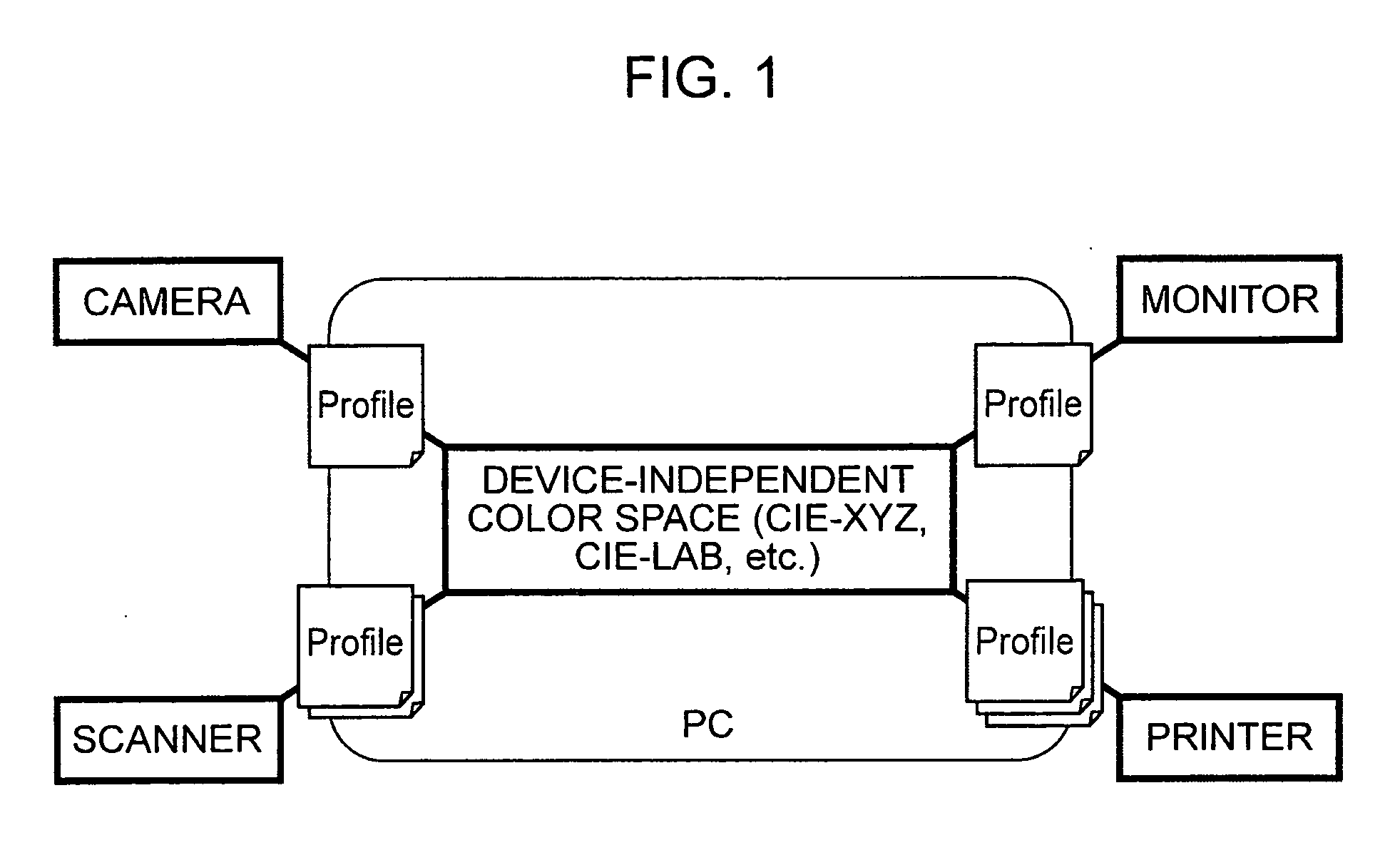
BACKGROUND OF THE INVENTION [0001] 1. Field of the Invention [0002] The present invention relates to image processing methods, profile creation methods, and image processing apparatuses, and particularly to techniques for defining a device-independent color space used in color conversion using profiles. [0003] 2. Description of the Related Art [0004] With the proliferation of digital devices, such as digital cameras and image scanners, digital images have become readily available in recent years. At the same time, full-color hard-copying technologies have been developed rapidly. In particular, inkjet printing technologies offer print image quality nearly equivalent to that of silver halide film cameras. Moreover, the Internet and other network technologies provide an environment where a variety of input and output devices can be connected to networks. In such an environment where various input and output devices are available, there are cases in which color image signals displayed, ...

Claims


Application Information

Patent Timeline
Patent Type & Authority Applications(United States)
IPC IPC(8): H04N1/60
CPCH04N1/6058
Inventor HORI, AYUMIKAWAI, YOSHINORIYAMAZOE, MANABU
Owner CANON KK
Learn More